- Protocols

- Articles and Issues
- For Authors
- About
- Become a Reviewer

Protocol for Imaging the Same Class IV Neurons at Different Stages of Development
Published: Vol 14, Iss 16, Aug 20, 2024 DOI: 10.21769/BioProtoc.5052 Views: 1317
Reviewed by: Nafisa M. JadavjiEhsan KheradpezhouhAnonymous reviewer(s)
Original research article
The authors used this protocol in:
Jun 2022

Protocol Collections
Comprehensive collections of detailed, peer-reviewed protocols focusing on specific topics


Abstract
In this protocol, we focused on analyzing internal branches of Drosophila class IV neurons. These neurons are characterized by their highly branched axons and dendrites and intricately tile the larval body. As Drosophila larvae progress through developmental stages, the dendritic arbors of Class IV neurons undergo notable transformations. As Drosophila larvae develop, their Class IV dendritic arbors grow. In the initial 24 h after egg laying (AEL), the dendrites are smaller than segments. During the subsequent 24 h of the first instar larval stage, dendritic arbors outpace segment growth, achieving tiling. After 48 h, arbors and segments grow concurrently. Epidermal cells near Class IV dendrites expand in proportion to segment growth. This observation suggested that Class IV cells might grow via branch dilation—uniformly elongating branches, akin to Class I cells [1,2]. To understand whether the class IV complex arbor structure is formed by dilation or simply from growing tips, we developed this protocol to introduce a systematic approach for quantitatively assessing the growth dynamics of internal branches.
Key features
• This protocol employs imaging the same neuron over different development times
• Drosophila embryo and larvae genotype is ;;ppkCD4-tdGFP, which explicitly tags class IV neurons
• This protocol for the preparation of agar pads to mount and image Drosophila larvae is adapted from Monica Driscoll's method
• Neurons are imaged without the use of anesthetics and for a short duration of time
• This technique involves the use of a spinning disk confocal microscope
Keywords: Class IV neuronsGraphical overview
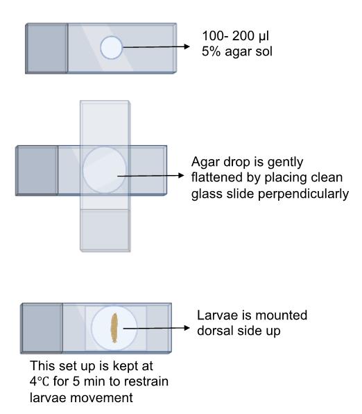
Schematic overview of the process for mounting larvae on an agar pad for imaging using a confocal microscope
Background
Dendrites serve as extensions of neurons and play a pivotal role in receiving signals from other neurons or the surrounding environment. These extensions often have a branched structure, which enhances their capacity to gather information. An excellent model for exploring the development of dendrites is found in the extensively branched Drosophila Class IV neurons. These neurons exhibit a wide array of shapes in their dendritic structures, with each dendrite being unique. This suggests that the growth of dendrites is more likely a random process rather than a predetermined one.
Despite this diversity, the specific underlying mechanisms guiding the development of dendrites in these neurons remain largely unclear. The larval body is divided into segments, and each segment harbors a pair of class IV neurons. These neurons, in our hand, are first visible around 16 h after egg laying (AEL). At this stage, neurons are small as compared to their harboring segment, but they grow fast and catch up with growing segments. After that, neurons grow in proportion to the expansion of the segments [3]. This has led to the hypothesis that Class IV cells expand through branch dilation—that is, by uniform expansion of branches along their lengths [4]. Such dilation occurs in Class I cells [1]. To form the highly branched late-stage dendrite, dilation would need to be complemented by the formation of new branches on extant ones, to infill the structure.
Through our investigation, we have made a noteworthy observation: dendritic branches lengthen primarily through extension from their tips, rather than by expanding their non-terminal branches. We developed this protocol to image the same neurons over developmental time without the use of anesthetics. Our focus was to image neurons for short durations and take static images, placing larvae back in apple agar plates in the Darwin chamber at 25 °C so that neurons and larvae do not get stressed by continuous imaging and use of anesthetics. The LarvaSPA method [5] allows imaging neurons continuously for 10 h; however, our goal was to image the same neuron every 24 h at various developmental time points.
Materials and reagents
Biological material
Fly line ;;ppk-cd4-tdGFP (homozygous) was used to image class IV dendritic arborization neurons and was a gift from C. Han (Cornell University)
Apple juice unsweetened frozen concentrate (4×) [Stop & Shop (grocery store), 12 oz can]
Dextrose (Sigma-Aldrich, catalog number: G5767)
Sucrose (Sigma-Aldrich, catalog number: 57-50-1)
Bacto agar (Becton Dickinson, catalog number: 214010)
NaOH pellet (Sigma-Aldrich, catalog number: 221465)
Propionic acid (Sigma-Aldrich, catalog number: 402907)
Phosphoric acid (Sigma-Aldrich, catalog number: 695017)
Halocarbon oil 700 (Sigma-Aldrich, catalog number: H8898)
Agarose (AmericanBio, catalog number: AB9012-36-6)
PBS 10× solution (AmericanBio, catalog number: AB11072-01000)
High-precision microscope cover glass 22 × 22 mm (VWR International, catalog number: 16004-302)
35 mm dish, No. 1.5 coverslip 10 mm glass diameter uncoated (MatTex, catalog number: P35G-1.5-10-C)
Mini embryo collection cages (Flystuff.com) (Genesee Scientific, catalog number: 59-105)
Tissue culture dish, 35 × 10 mm style (Falcon, catalog number: 353001)
Tray of 100 NARROW 1-oz PS vials, each with 10 mL of glucose media, pre-loaded with cellulose-acetate plugs (Archon Scientific, catalog number: D20102)
Frosted micro slides (VWR, catalog number: 48312-004)
Equipment
For imaging, samples were mounted on the microscope stage, illuminated with Nikon lasers (488 nm at 18%–21% laser power), and imaged on a spinning disk microscope: Yokogawa CSU-W1 disk (pinhole size 50 μm) built on a fully automated Nikon TI inverted microscope with perfect focus system, an sCMOS camera (Zyla 4.2 plus sCMOS), and Nikon Elements software with either a 40× (1.25 NA) or 20× (0.5 NA) water immersion objective.
Software and datasets
Images were stitched and analyzed using Fiji (NIH, 2021). Detailed procedure of stitching is mentioned in the procedure section. https://imagej.net/software/fiji/
NIS-Elements Imaging Software (Nikon, 2022 This imaging software comes with the spinning disk microscope. It is an interface that enables the user to capture images using Nikon microscope and also helps to export the raw images in the TIFF format, which could later be processed by FIJI for stitching
Prism 9 (GraphPad Prism, 2023). https://www.graphpad.com/scientific-software/prism/
Procedure
This protocol for the preparation of agar pads to mount and image Drosophila larvae is adapted from Monica Driscoll's method (https://www.wormatlas.org/agarpad.htm) [7].
Preparing an agar pad for larvae imaging
Measure and dissolve agar in water to create a 5% agar solution. Utilize a heat block to maintain the solution's molten state at a steady 65 °C. This temperature ensures the agar remains in a liquid state for the subsequent steps.
Application of agar solution: Using scissors, cut the tip of a 1000 mL pipette to allow controlled dispensing. Pipette 100–200 mL of molten agar onto the center of a pristine glass slide, ensuring a smooth and even distribution.
Formation of the agar pad: Place another clean glass slide perpendicular to the one with the agar drop, creating a "sandwich" effect. Gently press the top slide to flatten the agar, forming a circular pad. Pay close attention to avoid trapping air bubbles within the agar during this process, as they can interfere with imaging.
Optimal technique: For a more precise agar pad suitable for imaging larvae, follow Monica Driscoll's method. This technique involves using two additional taped slides, ensuring a flat surface without any irregularities that might hinder the larvae's movement or positioning.
Solidification and separation: Allow the agar to solidify naturally. Carefully separate the slides, ensuring that the agar pad adheres to one of them without any damage or distortion.
Timely preparation: It is crucial to prepare the agar pad just before use to maintain its optimal consistency and prevent it from drying out, which could affect its efficacy as a base for imaging.
Halocarbon application: Before mounting the larvae for imaging, add a drop of Halocarbon 700 onto the agar pad. Spread the halocarbon evenly across the surface to ensure proper lubrication and facilitate smooth movement of the larvae during imaging.
Chilling for optimal performance: To further enhance the agar pad's performance, chill it at 4 °C for approximately 5 min before mounting the larvae. This step can assist in achieving better adherence and stability.
Mounting of live larvae
Preparation of larvae: Wash the larvae sequentially with 20% and then 5% sucrose solutions to ensure cleanliness and hydration.
Positioning on agar bed: Gently place the larvae, dorsal side up, onto a 5% agar bed secured on a glass slide. Create an imaging environment by adding a drop composed of 50% PBS and 50% Halocarbon oil 700.
Immobilization technique: Further immobilize the larvae by applying gentle pressure with a 22 × 22 mm coverslip lined with Vaseline or vacuum grease.
Temperature optimization: Allow the setup to rest at 4 °C for 5 min to enhance stability.
Optional temperature control for reduced movement: Optionally, minimize larval movement during imaging by maintaining a temperature of 4 °C for 2–5 min. Employ an OKO lab temperature control module connected to a spinning disk confocal microscope (Nikon) for this purpose.
Image acquisition: Samples were imaged using a sophisticated spinning disk microscope setup, incorporating a Yokogawa CSU-W1 disk with a 50 μm pinhole size. The agar pad setup was mounted on a fully automated Nikon TI inverted microscope, equipped with perfect focus capabilities. For illumination, a 488 nm laser was used at a power setting of 18%–21%. The imaging was performed using either a 40× water immersion objective or a 20× air objective. The detection system included an sCMOS camera (Zyla 4.2 plus) and was controlled using Nikon Elements software.
Prior to image acquisition, samples were manually focused to accurately identify the abdominal third and fourth segments (A3 or A4 neurons). Static images intended for morphometric studies were captured using the 40× water immersion objective for larvae that were 24 h AEL, while the 20× objective was utilized for imaging larvae at later stages (such as 48, 72, and 96 h AEL). To create comprehensive images, the individual images were stitched together using the stitching plugin available in ImageJ software [6].
Post-imaging procedure: Return the imaged larvae to an apple agar plate containing yeast paste within a Darwin chamber set at 25 °C. Conduct a subsequent imaging session after 24 h, allowing for the continuous observation of the same class IV neuron throughout larvae development without the use of an anesthetic.
Protocol for stitching microscope images using FIJI plugin
This protocol is used to stitch microscope images using the FIJI plugin's "Stitch Directory with Images (unknown configuration)" under the Deprecated section. This process is suitable for combining multiple images into a single cohesive image, especially when the configuration of the images is not known beforehand.
Requirements: FIJI (Fiji Is Just ImageJ) software installed and a directory containing microscope images to be stitched.
Steps:
Open FIJI: Launch the FIJI software on your computer.
Prepare your images: Ensure all the images you want to stitch are in a single directory.
Verify that the images have consistent naming conventions for easier processing.
Access the stitching plugin: Go to Plugins in the menu bar. Navigate to Stitching and then select Stitch Directory with Images (unknown configuration). Select the Image Directory:
A dialog box will appear prompting you to select the directory containing your images (Figure 1).
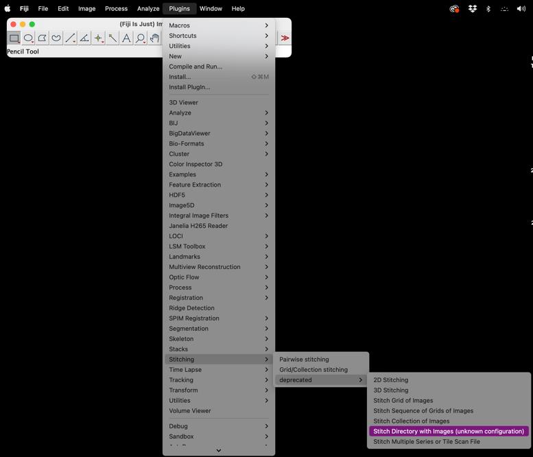
Figure 1. Screenshot of FIJI Software highlighting access to the stitching pluginClick Browse or Choose and navigate to the folder where your images are stored.
Select the directory and click OK (Figure 2).
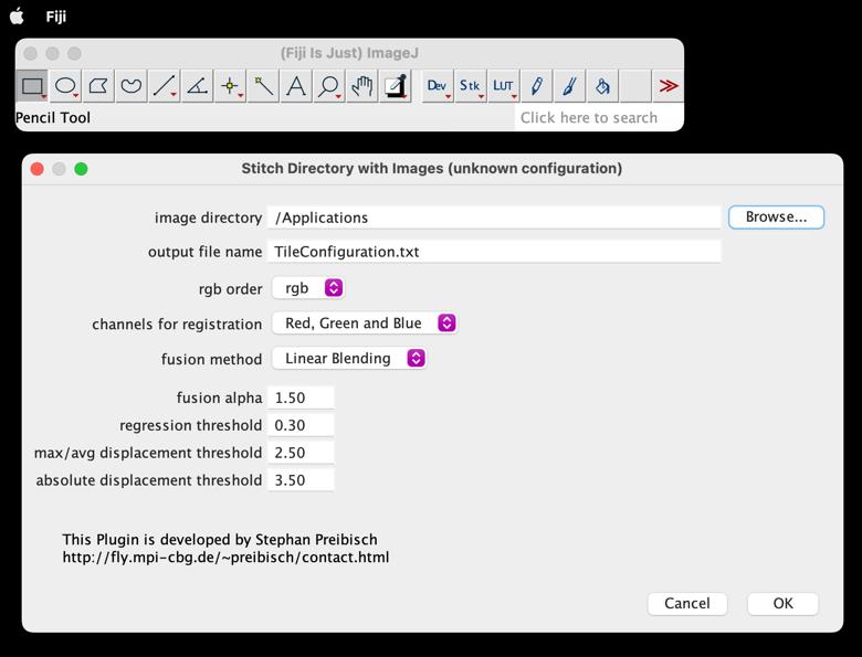
Figure 2. Snapshot of FIJI Stitching window demonstrating access to the image directoryFusion Method: Choose the method for merging images; typically, "Linear Blending" or "Max Intensity" work well.
Start stitching: Once all parameters are set, click OK to begin the stitching process.
FIJI will process the images; this may take some time depending on the number and size of images.
Review the stitched image: After the process is complete, the stitched image will be displayed. Inspect the image for any stitching errors or misalignments. If adjustments are necessary, you can tweak the parameters and repeat the process.
Save the stitched image: Once satisfied with the stitched result, go to File > Save As.
Choose the desired file format and location to save your stitched image.
Post-processing (Optional): Perform any additional image processing if required, such as cropping, adjusting contrast, or applying filters using FIJI.
Tips: For best results, ensure your images have consistent exposure and focus.
If the images have significant overlap, reduce the overlap percentage to speed up processing.
Save intermediate results periodically to avoid data loss in case of software crashes.
By following these steps, you should be able to successfully stitch microscope images using the FIJI plugin, even when the configuration of the images is unknown (Figure 3).
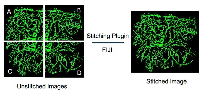
Figure 3. Overview of stitching microscope images using the FIJI stitching plugin. In this example, four side images are taken using the soma of a neuron as the reference point. The images are then stitched together to generate a complete view of the neuron.After stitching, segment/crop the neuron using FIJI’s Image and then Crop function.
Validation of protocol
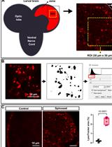
This protocol was used to visualize the same class IV neuron (A3 and A4 segments) at discrete times over development, at 24 and 48 h and at 48 and 96 h, to test whether arbor expansion of neurons is by dilation of internal branches or tip growth and infilling. The larvae were mounted on an agar pad and imaged as described above, without using anesthetics. To minimize movement, imaging was performed at 4 °C for 2–5 min. After imaging, the larvae were returned to an apple agar plate in the Darwin chamber. The imaging was conducted using 20× and 40× objectives.
For image analysis, the same neurons imaged at 24 and 48 h (Figure 4) were segmented (FIJI/Image/Crop) and aligned (FIJI/Image/Rotate) using ImageJ software. This alignment allowed us to identify conserved non-terminal internal branches in the proximal region. This detailed approach enabled a precise study of the potential role of internal branch elongation in arbor growth. The fractional increases in branches and segment lengths were defined as
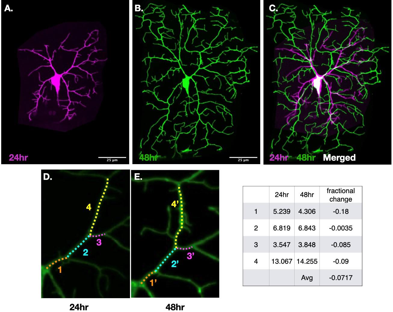
Figure 4. The same neuron imaged at 24 h (A) and 48 h (B) after egg laying (AEL) was segmented and aligned using ImageJ. Conserved internal branches were identified by overlaying the aligned images over each other using FIJI image tab and overlay tool (C) and marked with the same color-coded dotted lines and corresponding numbers (D&E). The length was measured using FIJI’s segmented line tool. The table on the right displays the lengths of these conserved internal or non-terminal branches along with their fractional length changes.
The detail of data analysis of this method is also described in the Result section “Dendrite growth is not due to elongation of all branches in the arbor” and Figure 2 of Shree et al., 2022 [6]. Our measurements of internal branches of the same class IV neurons over developmental time using an agar pad method were also consistent with earlier assessments done by Baltruschat et al. [8].
General notes and troubleshooting
This protocol was designed specifically to visualize the consistent observation of class IV neurons located on the dorsal side of Drosophila larvae at discrete developmental stages (24, 48, and 96 h after egg laying). The focus was solely on class IV neurons within the A3 and A4 abdominal segments.
Image the larvae for not more than 2–5 min as long-term imaging could stress larvae, which might halt their growth.
Following imaging sessions, it is crucial to promptly return the larvae to their apple agar plates and transfer them back into Darwin incubators set at 25 °C. This swift return process aids in maintaining the natural developmental conditions for the larvae. Use a paintbrush to pick larvae instead of tweezers for gentle handling, as Class IV neurons are highly sensitive to mechanical pressure; excessive pressure can halt their growth and lead to neuron degeneration. During imaging, larvae were immobilized with minimal pressure under a coverslip and positioned on an agar pad.
Emphasize speed: To preserve the integrity of observations and ensure consistency in developmental stages, prioritize the quick and efficient return of larvae to the apple agar plates post-imaging.
Acknowledgments
This study was supported by NIH grants DP1 MH110065 and R01 NS118884 awarded to Jonathon Howard. The abbreviated version of this protocol is published in Science Advances, Jun 2022. DOI: 10.1126/sciadv.abn0080.
Competing interests
The authors declare that they have no competing interests.
References
- Palavalli, A., Tizón-Escamilla, N., Rupprecht, J. F. and Lecuit, T. (2021). Deterministic and Stochastic Rules of Branching Govern Dendrite Morphogenesis of Sensory Neurons. Curr Biol. 31(3): 459–472.e4. https://doi.org/10.1016/j.cub.2020.10.054
- Ferreira Castro, A., Baltruschat, L., Stürner, T., Bahrami, A., Jedlicka, P., Tavosanis, G. and Cuntz, H. (2020). Achieving functional neuronal dendrite structure through sequential stochastic growth and retraction. eLife. 9: e60920. https://doi.org/10.7554/elife.60920
- Parrish, J. Z., Xu, P., Kim, C. C., Jan, L. Y. and Jan, Y. N. (2009). The microRNA bantam Functions in Epithelial Cells to Regulate Scaling Growth of Dendrite Arbors in Drosophila Sensory Neurons. Neuron. 63(6): 788–802. https://doi.org/10.1016/j.neuron.2009.08.006
- Yang, W. K. and Chien, C. T. (2019). Beyond being innervated: the epidermis actively shapes sensory dendritic patterning. Open Biol. 9(3): e180257. https://doi.org/10.1098/rsob.180257
- Ji, H. and Han, C. (2020). LarvaSPA, A Method for Mounting Drosophila Larva for Long-Term Time-Lapse Imaging. J Visualized Exp. 156: e60792. https://doi.org/10.3791/60792
- Shree, S., Sutradhar, S., Trottier, O., Tu, Y., Liang, X. and Howard, J. (2022). Dynamic instability of dendrite tips generates the highly branched morphologies of sensory neurons. Sci Adv. 8(26): eabn0080. https://doi.org/10.1126/sciadv.abn0080
- Driscoll, M. (2006). Mounting Animals for Observation with Nomarski DIC Optics. In Shaham, S. (Eds), In Methods in cell biology WormBook, 1551–8507. https://www.ncbi.nlm.nih.gov/books/NBK19784/
- Baltruschat, L., Tavosanis, G. and Cuntz, H. (2022). A developmental stretch-and-fill process that optimises dendritic wiring. bioRxiv. 2020.07.07.191064. https://doi.org/10.1101/2020.07.07.191064.
Article Information
Publication history
Received: Jun 30, 2024
Accepted: Jul 12, 2024
Available online: Aug 2, 2024
Published: Aug 20, 2024
Copyright
© 2024 The Author(s); This is an open access article under the CC BY-NC license (https://creativecommons.org/licenses/by-nc/4.0/).
How to cite
Readers should cite both the Bio-protocol article and the original research article where this protocol was used:
- Shree, S. and Howard, J. (2024). Protocol for Imaging the Same Class IV Neurons at Different Stages of Development. Bio-protocol 14(16): e5052. DOI: 10.21769/BioProtoc.5052.
- Shree, S., Sutradhar, S., Trottier, O., Tu, Y., Liang, X. and Howard, J. (2022). Dynamic instability of dendrite tips generates the highly branched morphologies of sensory neurons. Sci Adv. 8(26): eabn0080. https://doi.org/10.1126/sciadv.abn0080
Category
Developmental Biology > Morphogenesis > Cell structure
Neuroscience > Cellular mechanisms > Neuronal fate
Cell Biology > Cell imaging > Confocal microscopy
Do you have any questions about this protocol?
Post your question to gather feedback from the community. We will also invite the authors of this article to respond.