- Protocols

- Articles and Issues
- For Authors
- About
- Become a Reviewer

Bi-directional Dual-flow-RootChip for Physiological Analysis of Plant Primary Roots Under Asymmetric Perfusion of Stress Treatments
Published: Vol 13, Iss 15, Aug 5, 2023 DOI: 10.21769/BioProtoc.4764 Views: 1996
Reviewed by: Anonymous reviewer(s)
Original research article
The authors used this protocol in:

Jan 2023
Advertisement


Protocol Collections
Comprehensive collections of detailed, peer-reviewed protocols focusing on specific topics


Related protocols

Abstract
Due to technical limitations, research to date has mainly focused on the role of abiotic and biotic stress–signalling molecules in the aerial organs of plants, including the whole shoot, stem, and leaves. Novel experimental platforms including the dual-flow-RootChip (dfRC), PlantChip, and RootArray have since expanded this to plant-root cell analysis. Based on microfluidic platforms for flow stream shaping and force sensing on tip-growing organisms, the dfRC has further been expanded into a bi-directional dual‐flow‐RootChip (bi-dfRC), incorporating a second adjacent pair of inlets/outlet, enabling bi-directional asymmetric perfusion of treatments towards plant roots (shoot-to-root or root-to-shoot). This protocol outlines, in detail, the design and use of the bi-dfRC platform. Plant culture on chip is combined with guided root growth and controlled exposure of the primary root to solute changes. The impact of surface treatment on root growth and defence signals can be tracked in response to abiotic and biotic stress or the combinatory effect of both. In particular, this protocol highlights the ability of the platform to culture a variety of plants, such as Arabidopsis thaliana, Nicotiana benthamiana, and Solanum lycopersicum, on chip. It demonstrates that by simply altering the dimensions of the bi-dfRC, a broad application basis to study desired plant species with varying primary root sizes under microfluidics is achieved.
Key features
• Expansion of the method developed by Stanley et al. (2018a) to study the directionality of defence signals responding to localised treatments.
Description of a microfluidic platform allowing culture of plants with primary roots up to 40 mm length, 550 μm width, and 500 μm height.
Treatment with polyvinylpyrrolidone (PVP) to permanently retain the hydrophilicity of partially hydrophobic bi-dfRC microchannels, enabling use with surface-sensitive plant lines.
• Description of novel tubing array setup equipped with rotatable valves for switching treatment reagent and orientation, while live-imaging on the bi-dfRC.
Graphical overview

Graphical overview of bi-dfRC fabrication, plantlet culture, and setup for root physiological analysis. (a) Schematic diagram depicting photolithography and replica molding, to produce a PDMS device. (b) Schematic diagram depicting seed culture off chip, followed by sub-culture of 4-day-old plantlets on chip. (c) Schematic diagram depicting microscopy and imaging setup, equipped with a media delivery system for asymmetric treatment introduction into the bi-dfRC microchannel root physiological analysis under varying conditions.
Background
Plant survival in abiotic and biotic stress conditions is linked with the ability to respond to the external environment through signal transduction (Lamers et al., 2020). Data supports that drought and pathogen infection are two environmental stressors with an unequivocal impact on worldwide crop, forestry, and ecosystem loss (Farooq et al., 2012; Nazarov et al., 2020). Despite the severe impact, our knowledge on how abiotic and biotic stress impact plant defence is limited. Plant growth, development, and adaptation are the outcome of a signalling process within the plant (Nejat and Mantri, 2017). Calcium is a universal signal known to modulate gene expression, hormone release, movement (e.g., muscles, stomata), and cell death (Noman et al., 2021), amongst other processes. Recent research has shown that calcium interacts with reactive oxygen species signalling, specifically hydrogen peroxide, during abiotic and biotic stress (Sewelam et al., 2016; Toyota et al., 2018). Additionally, interplay exists with downstream signals including nitric oxide and phytohormones (Freschi, 2013). However, it remains unclear how these signalling processes interact to regulate root growth and adaptation towards environmental stress. Based on a microfluidic platform for flow stream shaping on tip-growing organisms (Stanley et al., 2018a and 2018b), a refined and enhanced bi-directional dual‐flow‐RootChip (bi-dfRC) platform was established (Allan et al., 2022 and 2023). The bi-dfRC incorporates a second adjacent set of microchannel inlets/outlets connected to the base of the root observation channel for flow reversal. By combining plant culture on chip, root extension and directionality of cellular signalling responses towards local stress conditions can be tracked via controlled exposure of the root to solute changes, in a variety of combinations and spatial orientations. This protocol highlights the broad culture capabilities of the bi-dfRC towards multiple plant species including Arabidopsis thaliana, Nicotiana benthamiana, and Solanum lycopersicum. On chip root culture can also accommodate touch-sensitive transgenic plant lines through hydrophobic retention of PVP-treated microchannels. By simply altering the microchannel dimensions, the culture of plantlet primary roots up to 40 mm × 550 µm× 500 μm (length, width, height) into the bi-dfRC becomes possible, highlighting the flexibility of the platform. These measurements are the largest of interest to date; however, the technology is available to adapt and manufacture even larger devices, given compatibility with desired imaging setups. For sizeable devices that become impractical for photolithography master mold fabrication, millifluidics may be utilised via 3D printing (Kitson et al., 2012). The knowledge delivered by microfluidic technology provides insight into plant signal transduction and facilitates a platform for future research on root and plant stress perception. This may lead to novel insight towards physiological processes for improved plant tolerance towards both abiotic stress events and pathogens.
Materials and reagents
Biological materials
Arabidopsis thaliana Columbia-0 (Col-0) wild-type seeds (in-house propagated)
Nicotiana benthamiana seeds (in-house propagated)
Solanum lycopersicum Money Maker seeds (Bunnings, Country Value, catalog number: 2961272)
Reagents
Negative-tone photoresist (DJMicrolaminates, Suex, catalog number: SUEX 100)
Photoresist developer (Microchemicals, catalog number: AZ326-MIF)
Chromium etchant solution (Sigma-Aldrich, catalog number: 651826)
Propylene glycol methyl ether acetate developer (Sigma-Aldrich, catalog number: 484431)
Isopropanol (Sigma-Aldrich, catalog number: I9516)
Acetone (Sigma-Aldrich, catalog number: 90872)
Methanol (Sigma-Aldrich, catalog number: 34860)
Anti-adhesion agent Trichloro (1H,1H,2H,2H-perfluorooctyl) silane (Sigma-Aldrich, catalog number: 48931)
Polydimethylsiloxane pre-polymer silicone elastomer base and silicone elastomer curing agent (Sigma-Aldrich, Sylgard 184, Electropar, catalog number: 761028-5EA)
Deionized water (Lab made)
Sudan blue dye (Sigma-Aldrich, catalog number: 306436)
Toluene (Sigma-Aldrich, catalog number: 244511)
Norland Optical Adhesive (AusOptic, Norland Products, catalog number: NOA-72)
Triton X-100 (Sigma-Aldrich, catalog number: X100)
Ethanol (70%) (Sigma-Aldrich, catalog number: 1.00986)
Polyvinylpyrrolidone (Kollidon) (Sigma-Aldrich, catalog number: 02286)
Murashige and Skoog medium (Duchefa, catalog number: MFCD00240976)
Plant agar (GoldBio, catalog number: P1001.0100)
2-ethanesulfonic acid (MES) (Sigma-Aldrich, catalog number: M3671)
Janola Liquid Bleach (40%) (OfficeMax, catalog number: 2233630)
Potassium hydroxide (10 M) (Sigma-Aldrich, catalog number: 06103).
Solutions
Polyvinylpyrrolidone (22% w/v) (see Recipes)
Half-strength (½) Murashige and Skoog medium with 3.1 mM MES liquid medium (see Recipes)
Plant agarose (see Recipes)
Half-strength (½) Murashige and Skoog with 0.31 mM MES plant agarose (see Recipes)
Recipes
Polyvinylpyrrolidone (22% w/v)
Reagent Final concentration Amount Kollidon 22% 2.22 g Deionized water n/a 10 mL Total 22% 10 mL Half-strength (½) Murashige and Skoog medium with 3.1 mM MES liquid medium
Reagent Final concentration Amount Murashige and Skoog ½ 6.084 g MES 3.1 mM 3.026 g Water (ultrapure) n/a 500 mL Total 10× 500 mL *Adjust pH to 5.6 using 10 M potassium hydroxide. For a 1× working concentration, dilute 1:10 ½ Murashige and Skoog with 3.1 mM MES in water (ultrapure). Autoclave at 121 °C for 1 h.
Plant agarose (1%)
Reagent Final concentration Amount Plant agar 1% 5 g Water (ultrapure) n/a 500 mL Total 1% 500 mL *Autoclave at 121 °C for 1 h.
Half-strength (½) Murashige and Skoog with 0.31 mM MES plant agarose
Reagent Final concentration Amount Murashige and Skoog ½ 100 mL MES 3.1 mM 100 mL Water (ultrapure) n/a 300 mL Plant agar 1% 500 mL Total 1× 500 mL *Add liquid media to pre-cooled molten plant agar and mix well.
Laboratory supplies
Photo-masks (Nanofilm, catalog number: 4 × 4 × 0.060 SL LRC 10M 1518 5K)
Single-side polished silicon wafers 4" (Prime grade, WaferPro, catalog number: J204001)
Polyethylene sheets (OfficeMax, Overhead Projector Transparency Film A4, catalog number: 1219839)
Poly (methyl methacrylate) ring (lab-made cast acrylic, Mulford Plastics)
100 mm × 100 mm × 3 mm thick steel slab (Lab made, Nzsteel)
26 mm × 60 mm glass microscope slides (Lab Supply, catalog number: MAR0101030)
Vacuum-sealable food storage bags (Noel Leeming, Sunbeam, catalog number: VS0520)
Seed raising soil mix (Mitre 10, Tui, catalog number: TSEE1533)
Vermiculite (Mitre 10, Garden Highlights, catalog number: GHVER05)
A4 and A3 paper (OfficeMax, catalog numbers: 2220938 and 2220350, respectively)
Photolithography mask aligner filter PL-360LP (Omega Filters, catalog number: W2927)
Plastic incubation chambers (Thermo Fisher Scientific, NuncTMOmniTrayTMSingle-Well Plate, catalog number: 242811)
Scalpel with No. 10 blade (OfficeMax, Swann Morton, catalog number: 2208318)
Hole punch Ø 1 mm, 3 mm, 5 mm (ProSciTech, catalog numbers: T983-10, T983-30, and T983-50, respectively)
10 mL glass test tube (Sigma-Aldrich, catalog number: CLS9944513)
Dome propagator (Mitre 10, Otaki Hydroponics, catalog number: TG3104013)
7.5 cm × 10 cm, 750 mL, and 15 L plastic growth pots (Mitre 10, IP Plastics, catalog numbers: 169840, 283255, and 283269, respectively)
Plastic seed collection base equipped with plastic sheath (Arasystem, catalog number: ASN002, Aracons 720)
90 mm round Petri dish (Thermo Fisher Scientific, catalog number: 101VR20)
8 cm metal sieve (Stevens, Capital Kitchen, catalog number: 6546448)
Toothpicks (Discount Office, Gilmours, catalog number: GL1010819)
1.5 mL microcentrifuge tube (Thermo Fisher Scientific, Eppendorf, catalog number: 0030125150)
Sealing film (Sigma-Aldrich, Parafilm, catalog number: HS234526C-1EA)
5 mL syringe (Amtech, catalog number: 302135)
Ethylene tetrafluoroethylene tubing OD 1/16" (Kinesis, catalog number: 1517L)
Platinum-cured silicon tubing (Darwin Microfluidics, catalog number: SHE-TUB-SIL-1*1)
Stainless steel 90° bent polydimethylsiloxane couplers (Lab made, Darwin Microfluidics, catalog number: PN-BEN-18G-20)
Flangeless fittings (¼-28, Kinesis, catalog number: XP-235x)
Quick Connect Luer adapters (Scientificlabs, Kinesis, catalog number: P-628)
4× 200 mm × 20 mm × 20 mm Aluminium V slot extrusion (Aluminium Extrusion Company)
4× 300 mm × 20 mm × 20 mm Aluminium V slot extrusion (Aluminium Extrusion Company)
4× 20 series Corner Bracket 3 way (Aluminium Extrusion Company)
1× 200 mm × 200 mm Poly (methyl methacrylate) sheet (Lab made, Sigma-Aldrich, catalog number: GF53167608)
4× 1 mm Aluminium L brackets (Lab made; Aluminium Extrusion Company)
20× 20 series T Slot Spring Nuts - M4 (Aluminium Extrusion Company)
Low Pressure Unions (Kinesis, catalog number: P-702)
High-performance liquid chromatography 4-way manual switching valves (Kinesis, catalog number: V-100D)
Equipment
Laser mask writer Heidelberg μPG101 (Heidelberg Instruments)
Convection oven (Thermo Fisher Scientific, Heratherm, catalog number: 51028112)
Oxygen plasma cleaner (Tergeo, PIE Scientific)
Sky-335R6 laminator (SkyDSB)
MA-6 Mask aligner (SUSS MicroTec)
Hot plate (Torrey Pines Scientific, catalog number: HS40)
Desiccator (Sp bel-art, catalog number: F42020-0000)
Vacuum pump (VABS Ltd, catalog number: TC-2000VS)
Fumigation hood (Thermoplastic Engineering, Xtracare VSS)
S2000 ultraviolet curing system (Polydispensing, OmniCure®)
Pressurised nitrogen gun (Vacuum, BLOVAC)
Guillotine/LC slicer (Lucy Clay, catalog number: V5)
Ultra sonication bath (Lab Supply, catalog number: ELM1005507)
Vacuum sealer (Harvey Norman, Foodsaver, catalog number: VS4500)
Growth chambers (Aralab, Fitoclima, catalog number: 600)
Laminar flow hood (LaboGene, ScanLaf)
Programmable Syringe Pump PHD2000 70-2001 (Darwin-microfluidics, Harvard Apparatus, catalog number: HA-70-3007)
Epifluorescence microscope (Zeiss, catalog number: AX10)
Software
L-Edit IC Mentor Graphics Siemens EDA (v2020.1, July 2020)
Fiji, ImageJ (2.9.0, September 2022)
ZEN 2 Blue Zeiss (v3.0, October 2022)
Procedure
Photolithography and replica molding
Design the bi-dfRCs in software (L-Edit IC, v2020.1) (Figure 1a–1c; Supplemental Files 1–3).
Note: Supplemental Files 1–3 are in .dxf format and can be viewed in the software eDrawings Viewer or modified in SolidWorks/Fusion360 (the latter is free for educational use).
Transfer the pattern onto a photomask blank via laser mask writer.
Position the photomask blank with AZ1518 photoresist layer onto the stage of a laser mask writer.
Turn on the laser mask writer exposure.
Develop the photomask in AZ326-MIF photoresist developer, for 1 min, at room temperature.
Rinse the photomask with deionized water to stop development and then dry with a nitrogen gun.
Note: Ensure that the photomask is thoroughly rinsed for at least 1–2 min during this process.
Transfer the etched features of the bi-dfRC into the photomask via chrome etching.
In an acid fume hood, submerge the fully developed photomask in chromium etchant solution, with manual agitation, for 1 min.
Rinse the photomask with deionized water to stop etching and then dry with a nitrogen gun.
To remove residual photoresist, rinse the photomask with acetone followed by methanol and isopropanol for 5 min each in a sonication bath.
Note: This process yields a photomask containing fully developed etched features of the bi-dfRC microchannels. This mask can be re-used multiple times.
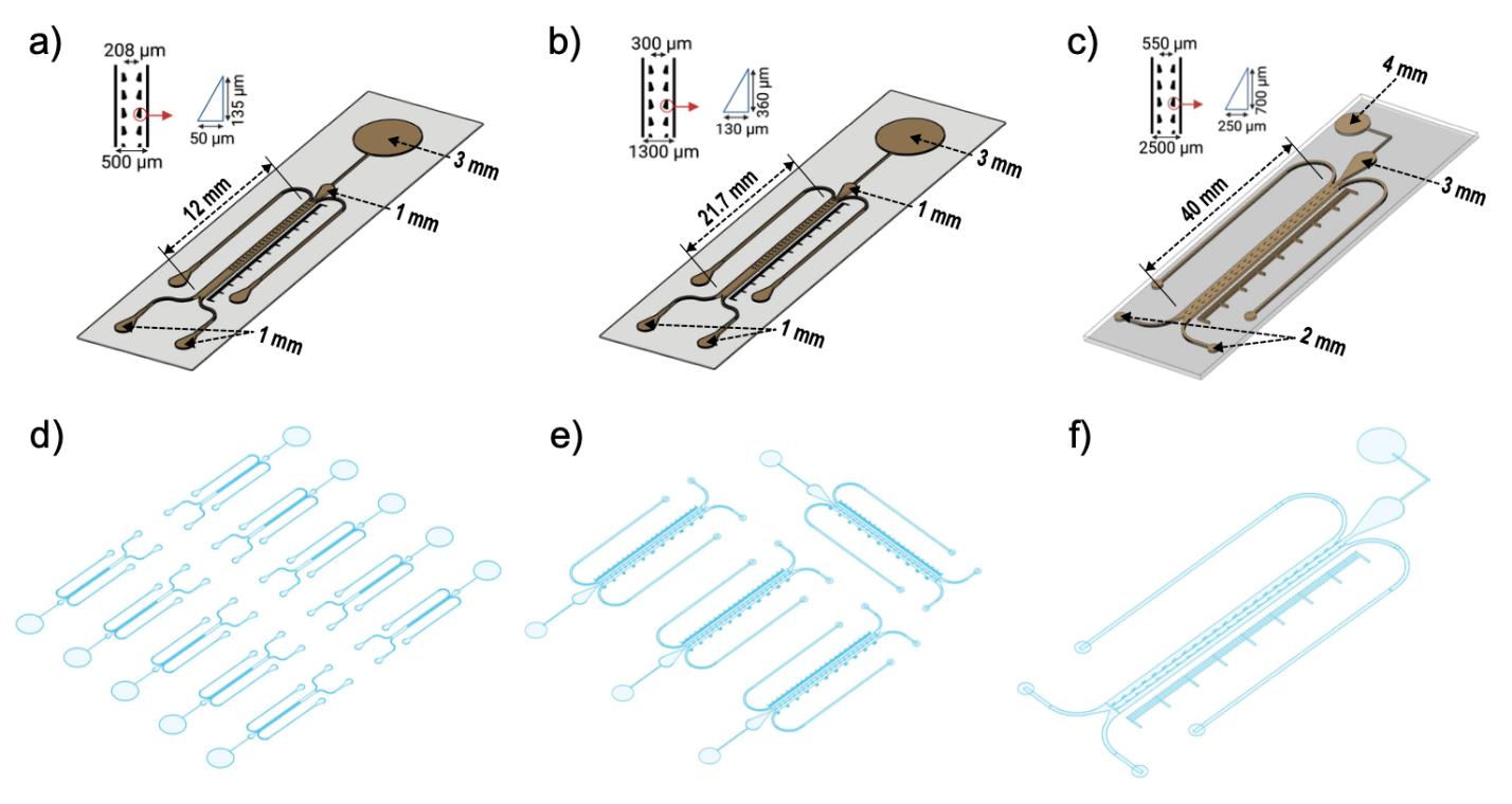
Figure 1. Key dimensions of the bi-dfRC platform, including inlet diameters and length of the root guidance array in the observation channel (OC) for different plants. All diagrams have been scaled to size, for visualisation purposes. Schematic diagrams depicting the key dimensions of the A. thaliana bi-dfRC (a), the N. benthamiana bi-dfRC (b), and the S. lycopersicum bi-dfRC (c). Visual representation of the wafer designs/mold pattern presented in Supplemental Files 1-3 for (d)A. thalianabi-dfRCs, (e) the N. benthamiana bi-dfRCs, and the S. lycopersicum bi-dfRC (f).
Wafer lamination
Dehydrate a 4" single-side polished silicon wafer at 180 °C for 24 h in a convection oven.
Remove the silicon wafer using protective gloves and cool until safe to handle. Critical step: Avoid leaving wafer at room temperature for extended periods to avoid adsorption of moisture.
Clean the silicon wafer in a plasma cleaner.
Set the run cycle to a power of 100 W, pulse ratio of 255, and 5 standard cubic centimetres per minute (sccm) of oxygen for 10 min.
Laminate negative-tone dry film photoresist to wafer (Data Sheets/ResearchPapers, 2020).
Set the laminator rollers to 65 °C and speed 1.
To avoid displacement while laminating, align the wafer on an aluminium sheet with raised stoppers.
Partially cover the wafer with a first polyethylene sheet.
Remove bottom protective cover off the photoresist and place the exposed side onto the polyethylene, partially overlapping the wafer.
Cover with a second polyethylene sheet fixed to the aluminium sheet.
Pass the setup under the rollers, removing the first polyethylene sheet in the process. Critical step: Stop the first polyethylene sheet from entering between the rollers to prevent it from sticking to the wafer.
Remove laminated wafer and bake on a hotplate at 65 °C for 15 min.
Mold fabrication
Power on the mask aligner.
Note: Allow the mask aligner to warm up for ~30 min.
Using an ultraviolet intensity meter with a p365 nm sensor, check the ultraviolet intensity at the wafer holder.
Set a fitted dose of 166.6 mJ/cm2 at 365 nm, based on a dry film resist thickness of 100 μm, yielding a run time of 1,170 s (Data Sheets/ResearchPapers, 2021).
Set a soft-contact run to multi-exposure for 10 s consecutive intervals with 1 min breaks, for 17 repeats.
Note: This will prevent overheating of the photoresist, reducing mechanical stress within the cross-linked resist on the silicon wafer.
Load the bi-dfRC mask.
Position a photolithography mask aligner filter over the setup.
Remove the top protective cover off the photoresist.
Place the silicon wafer with the photoresist facing up onto the wafer holder of the mask aligner.
Apply vacuum to the wafer holder, secure, close, and then start the pre-set mask aligner run.
Post-exposure bake the exposed silicon wafer on a programmable hotplate, set to a cycle of 5 min at 65 °C, 20 min at 95 °C, and then 20 min at 20 °C. Critical step: Perform bake directly after exposure. Use a low ramping speed (15 °C/h) for the cool down step to reduce mechanical stress.
Place the silicon wafer feature-side down onto a stainless-steel mesh submerged in propylene glycol methyl ether acetate developer, for 30 min or until fully developed.
Wash the silicon wafer with fresh propylene glycol methyl ether acetate and isopropanol for 5 min.
Hardbake the silicon wafer on a programmable hotplate for 1 h at 125 °C and then 20 min at 20 °C. Critical step: Use a low ramping speed (15 °C/h) for the cool down step to reduce mechanical stress.
Note: After concluding photolithography, a silicon wafer with the bi-dfRC photo-developed structures is produced. The silicon wafer is used as a casting mold for soft lithography (Figure 2a–2c). Due to the different root sizes, one A. thaliana bi-dfRC wafer yields 10 microchannels, one N. benthamiana bi-dfRC wafer yields five microchannels, and one S. lycopersicum bi-dfRC wafer yields one microchannel.
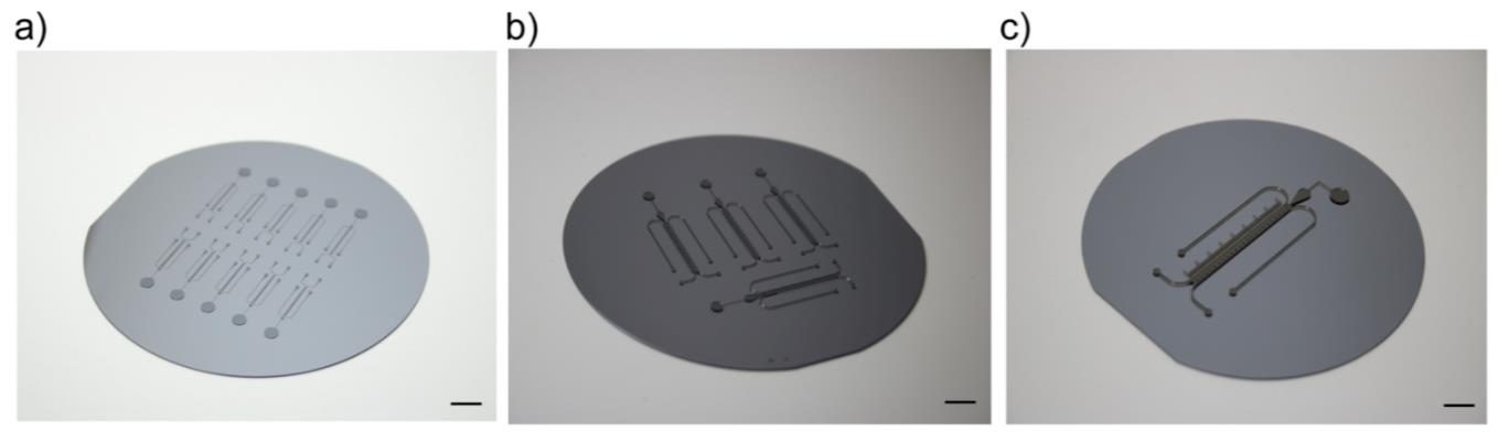
Figure 2. Silicon wafer molds, with bi-dfRC photo-developed structures. Scale = 10 mm. (a) Silicon wafer for the A. thaliana bi-dfRCs comprise of 10 individual chip structures. (b) Silicon wafer for the N. benthamiana bi-dfRCs comprise of five individual chip structures. (c) Silicon wafer for the S. lycopersicum bi-dfRCs comprise of one individual chip structure.
Silane treatment of mold wafer
Treat the silicon wafer with anti-adhesion agent.
Place the silicon wafer feature-side up into a vacuum desiccator.
Add one drop of Trichloro (1H,1H,2H,2H-perfluorooctyl) silane in an open glass shot bottle into the desiccator.
Apply vacuum pumping for 5 min.
Switch off the vacuum pump and keep the bi-dfRC mold in the desiccator under vacuum for 30 min.
Notes:
i. This will coat the silicon wafer and prevent sticking of the elastomer during subsequent soft lithography, protecting the photo-resist layer for repeated use.
ii. Silane treatment was repeated following 10 subsequent uses of the wafer as a mold for soft lithography.
Soft lithography
Mix polydimethylsiloxane pre-polymer silicone elastomer base together with curing agent in a plastic container in a 10:1 (w/w) ratio.
Place the mixture into a desiccator and apply vacuum for 30–60 min until bubbles have disappeared. Critical step: This will remove air bubbles from the mixture while assisting with solution mixing.
Cast the wafer mold.
Cover a 100 mm × 100 mm × 3 mm thick steel slab with a fresh polyethylene sheet and then place the silicon wafer atop, feature-side up.
Note: Steel slab dimensions may vary but should fit inside the desiccator.
Position a round 1.5 mm tall poly (methyl methacrylate) ring around the perimeter of the wafer.
Note: This will create a seal around the edge of the wafer to avoid polydimethylsiloxane leakage during casting.
Pour the pre-degassed polydimethylsiloxane mixture onto the silicon wafer.
Place a fresh polyethylene sheet ¾ covering the setup, followed by another 100 × 100 × 3 mm thick steel slab.
Note: This setup reduces pressure build up and adds a counterweight to hold the silicon wafer in place, while circumventing leakage of the polydimethylsiloxane between the poly (methyl methacrylate) ring and wafer.
Transfer the setup into a desiccator and apply vacuum for ~40 min until bubbles have disappeared. Critical step: This will assist with the removal of additional air bubbles formed during pouring the polydimethylsiloxane.
Transfer the setup from the desiccator to a hotplate set to 80 °C for 2 h.
Note: The polydimethylsiloxane will cure into an elastic solid.
Remove the poly (methyl methacrylate) ring from the edges of the wafer by gently probing the edges with a scalpel and then peel the polydimethylsiloxane off the wafer.
Note: Place the pre-cured polydimethylsiloxane between two fresh polyethylene sheets.
Bake the pre-cured polydimethylsiloxane on a hot plate for an additional 2 h at 80 °C.
Note: The second heating cycle improves the curing of the polydimethylsiloxane.
Allow the polydimethylsiloxane to cool; then, vertically punch the inlet/outlet channels with hole punches (1 mm for media inlets/outlets, 1–2 mm for the root inlet, and 3–4 mm for media port for all chip dimensions).
Notes:
i. Punch root inlets on an 135° obtuse angle from the glass base aligned with the feature pattern for optimal root growth into the bi-dfRC microchannel.
ii. To avoid the polydimethylsiloxane tearing, twist the hole punch gently during extraction.
Using a guillotine, cut away excess polydimethylsiloxane and separate the etched microchannels as desired.
Note: Arabidopsis bi-dfRC fit two microchannel patterns to one 26 mm × 60 mm glass microscope slide, or five microchannels to one 76 mm × 83 mm coverslip. Nicotiana benthamiana and Solanum lycopersicum bi-dfRCs fit one microchannel to one 26 mm × 60 mm glass microscope slide.
Plasma bonding
Pre-clean glass microscope slides in acetone, followed by methanol and isopropanol for 5 min each.
Place the glass slides and polydimethylsiloxane chips (feature-side up) onto the sample holder of a plasma cleaner.
Note: Place a polyethylene transparent film under the polydimethylsiloxane to prevent bonding to the sample holder.
Place the sample holder into the plasma cleaner.
Set to run at 15 W power, pulse ratio of 50, and 5 sccm of oxygen for 1 min.
Note: This will activate the bonding surfaces of the polydimethylsiloxane and glass.
Remove the sample holder from the plasma cleaner and then bond the activated side of the polydimethylsiloxane chips to the glass coverslips by lightly pressing the exposed surfaces together.
Note: If sub-optimal bonding occurs, see Troubleshooting 1.
Place the bonded bi-dfRC on a hotplate at 80 °C for 2 h.
Notes:
This final heat cycle strengthens the bond between the polydimethylsiloxane and glass.
For storage, place the bi-dfRCs in a desiccator for 3 h and then vacuum seal shut using vacuum-sealable food storage bags.
Polyvinylpyrrolidone treatment (optional)
Note: This procedure is utilised to permanently retain the hydrophilicity of the bi-dfRC microfluidic channels, to culture surface sensitive transgenic plant lines on chip, including G-CaMP3 Ca2+sensor lines (Allan et al., 2022 and 2023).
Place the completed bi-dfRCs in the plasma cleaner for 30 W power, pulse ratio 50, and 5 sccm of oxygen for 3 min.
Remove bi-dfRCs from the plasma cleaner.
Add a drop of 22% w/v polyvinylpyrrolidone onto the inlet of the bi-dfRC and then allow the solution to passively fill the microchannels.
Leave the polyvinylpyrrolidone in the microchannels for ≥ 1 min and then wash three times with deionized water.
Dry the microchannels with a nitrogen spray gun.
Place the bi-dfRCs under vacuum desiccation for 2–3 h.
Using a vacuum sealer, store the bi-dfRCs into any sturdy plastic container in a vacuum sealable food storage bag for up to one year.
Epoxy dye treatment (optional, for chip visualisation) (Soffe et al., 2020)
Dissolve 2 mg of Sudan blue dye in 1 mL of toluene in a glass test tube.
Add 250 μL of Norland Optical Adhesive with manual agitation.
Ultrasonicate the glass test tube for 10 min.
Evaporate off the toluene blue in a fume hood.
Store solution at 4 °C until use.
Pre-treat bi-dfRC microchannels in a plasma cleaner on run power 15 W, pulse ratio 50, oxygen flow rate of 3 sccm for a duration of 60 s.
Place the post-activated bi-dfRCs into a desiccator.
Add one drop of Trichloro (1H,1H,2H,2H-perfluorooctyl) silane in a glass shot bottle into the desiccator.
Apply vacuum pumping for 5 min.
Sit the bi-dfRCs in the desiccator with the lid on for 1 h without vacuum.
Note: This will allow the silane to coat the polydimethylsiloxane.
Clean the polydimethylsiloxane surface and microchannels of the bi-dfRCs with isopropyl alcohol and deionized water, for 5 min.
Dry the bi-dfRCs surfaces and microchannels with a pressurised nitrogen gun.
Place the bi-dfRCs in a desiccator for 2 h.
Note: Desiccation prior to adding the dye will remove the residual water absorbed by the polydimethylsiloxane substrate.
Using a pipette, add 60 μL of the epoxy dye onto the root inlet of the bi-dfRCs.
Note: Dye will passively enter the bi-dfRC microchannels.
Clean excess epoxy dye from the outside surface of the polydimethylsiloxane using isopropyl alcohol.
Expose the epoxy dye filled bi-dfRCs using an ultraviolet spot curing system, inverting each bi-dfRC every 2 h for the first 6 h of exposure, with the chip placed approximately 200 mm away from the light source.
Notes:
This technique allows for even exposure while ensuring rapid curing and minimisation of leeching into the polydimethylsiloxane.
This protocol obtains high-quality images of the microfluidic device, with detailed illustration of the microchannels (Figure 3a–3c).
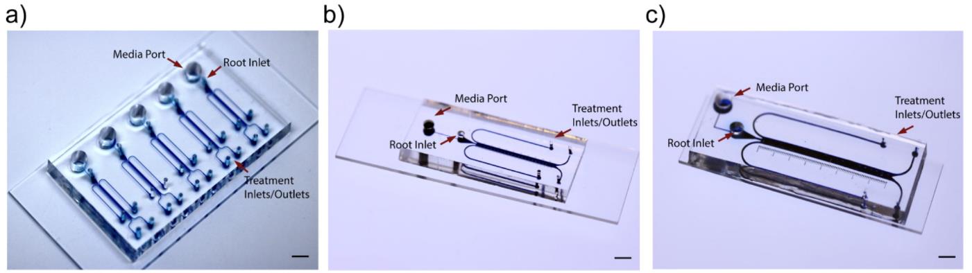
Figure 3. Epoxy dye (blue) filled microchannels of the bi-dfRCs, for visualisation. Scale = 5 mm. (a) Dyed microchannels of the A. thaliana bi-dfRCs. (b) Dyed microchannels of the N. benthamiana bi-dfRCs. (c) Dyed microchannel of the S. lycopersicum bi-dfRC.
Plant media preparation
Prepare half-strength (½) Murashige and Skoog medium with 3.1 mM MES in water (ultrapure) and adjust the pH of the solution to 5.6 (see Recipes).
Separately, prepare 1% plant agarose in water (ultrapure) (see Recipes).
Autoclave all media at 121 °C for 1–1.5 h.
Under a laminar flow, prepare ½ Murashige and Skoog with 0.31 mM MES plant agarose plates (see Recipes).
Note: Mixing of the stocks following autoclave allows for preparation of varying media concentrations, as desired. Alternatively, ½ MS/0.31 mM MES plant agar can simply be pre-prepared in a single bottle, prior to autoclave.
Under a laminar flow, pour 50 mL of media into each 90 mm diameter Petri dish and leave to solidify.
Seal the Petri dishes with parafilm.
Store at 4 °C until use.
Seed sterilisation and vernalisation
Add approximately 50 seeds into a 1.5 mL centrifuge tube.
Add 1 mL of 0.1% Triton X-100 for 4 min with manual agitation.
Note: For larger or rougher edged seeds (N. benthamiana and S. lycopersicum), add 40% bleach to the solution for 10–15 min.
Remove the detergent solution with a pipette without disrupting the seeds.
Add 70% ethanol for 2–5 min with manual agitation.
Remove the 70% ethanol without disrupting the seeds.
Wash the seeds four times with sterile water (ultrapure).
On the final wash, keep 500 mL of sterile water (ultrapure) in the tube.
Store the seeds in water at 4 °C for at least 12 h before use.
Note: Incubation in the cold induces vernalisation of the seeds, to accelerate flowering after planting.
Seed culture on agarose plates
Under a laminar flow, plate pre-sterilised and vernalised seeds onto ½ Murashige and Skoog with 0.31 mM MES plant agarose plates using a sterile toothpick.
Seal the Petri dishes with parafilm.
Incubate the agarose plates vertically, on a short-day growth cycle [8 h light (8 am), 16 h dark (4 pm)].
Note: Sub-culture A. thaliana onto the bi-dfRC following 5 days incubation, N. benthamiana following 10–14 days incubation, and S. lycopersicum following 4–5 days incubation. At this time, roots will be the optimal length to sub-culture into the bi-dfRC root inlet (n = 100, data not shown).
Plantlet culture on chip
Remove bi-dfRCs from the vacuum storage bag.
Under a laminar flow, surface sterilise the bi-dfRCs by exposure to ultraviolet light for 30 min.
Add 100 μL of 70% ethanol into the microchannels.
Note: This is a pre-sterilisation step to avoid microorganism growth during the subsequent incubation periods. If contamination prevails during incubation, see Troubleshooting 2.
Wash out the ethanol by adding 100 μL of sterile water (ultrapure) into the microchannel three times.
Replace the sterile water (ultrapure) with liquid ½ Murashige and Skoog with 0.31 mM MES media.
Using tweezers, place small pre-cut ½ Murashige and Skoog with 0.31 mM MES agarose squares (0.5 mm, width, length, and height) next to the root inlets of the bi-dfRCs.
Remove pre-cultured plants from incubation on agarose plates and subculture onto the bi-dfRC with tweezers.
Note: Position the primary root of the plantlet directly into the root inlet channel containing liquid ½ Murashige and Skoog with 0.31 mM MES media and then gently position the leaves onto the adjacent agarose square (Figure 4a–4f).
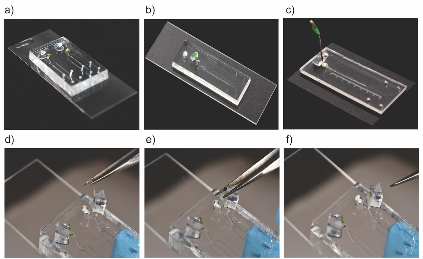
Figure 4. Plant culture onto the bi-dfRCs. Scale = 5 mm. (a) 9-day-oldA. thalianaroots cultured in the bi-dfRC observation channels. (b) 15-day-old N. benthamiana root cultured in the bi-dfRC observation channel. (c) 7-day-old S. lycopersicum root cultured in the bi-dfRC observation channel. Image series depicting the sub-culturing process of an A. thaliana root, firstly by aligning the plantlet at the pre-media-filled root inlet of the bi-dfRC (d), then gently situating the root tip into the root inlet (e), and finally resting the leaves onto a pre-cut agarose square (f).Place bi-dfRCs with cultured plantlets into NuncTM OmniTrayTM Single-Well Plates (plastic incubation chambers) with 10 mL of sterile water (ultrapure).
Note: This will create a humid environment for successful plantlet growth.
Seal the plastic incubation chambers with parafilm.
Incubate the plates on short-day growth cycle [8 h light (8 am), 16 h dark (4 pm)] until imaging via microscopy.
Notes:
Place the plastic incubation chambers containing cultured bi-dfRCs on a 45-degree angle to promote root growth into the observation channel.
A. thalianaroots will be ready to image from 8–10 days incubation, N. benthamiana roots will be ready to image from 15–17 days incubation, and S. lycopersicum roots will be ready to image from 7–10 days incubation (including the off-chip pre-incubation on agarose plates) (n = 100) (data not shown). The developmental stage of the primary root should show a defined tip, elongation zone, and differentiation zone of the root (root growth spanning up to 50% of microchannel).
Syringe pump system and tubing array for media injection into the bi-dfRC microchannels
Connect two plastic syringes onto a PhD 2000 Programmable Syringe Pump 70-2001 (multi syringe carrier capability) and set flow rate to 20 μL/min.
Note: Maintaining steady flow rate is important for the retention of asymmetric fluid flow in the bi-dfRC observation channels.
Connect the desired length of 1/16" OD ethylene tetrafluoroethylene tubing to the plastic syringes via Quick Connect Luer adapters with ¼-28 Flangeless fittings.
Construct the fluidic setup.
Build the flow matrix by positioning the components, including 4× high-performance liquid chromatography grade manual switching valves V-100D (solution and directional change valves), 4× Low Pressure Unions for the waste (W1A–1B and W2A–2B), and 4× Low Pressure Unions for chip connection (Inlet: I1–I2 and outlet: O1–O2) (Figure 5a–5b).
Join the components together with the desired lengths of ethylene tetrafluoroethylene tubing. Critical step: It is essential that the two circuits are comprised of equal tubing distances (for both circuits, use 33 cm of tubing between syringes and solution change valves, 24 cm between solution change valves and directional change valves, 15 cm between directional change valves and inlet fittings, 33 cm from the inlet fittings to the bi-dfRC inlets, 33 cm from bi-dfRC outlets to outlet fittings, 15 cm between outlet fittings and directional change valves, and 15 cm to the waste; tubing length optimised for the mounted solution delivery array described below) to avoid unequal fluidic resistances, ensuring that the test solutions arrive at the bi-dfRC observation channel simultaneously. For issues with uneven asymmetric flow rate, see Troubleshooting 3.
Optional: For ease, place the fluidic setup onto a raised mount.
Screw the Manual Switching Valves into a pre-cut plastic Poly(methyl methacrylate) lid with defined holes/inlets for the high-performance liquid chromatography valves.
Note: This will allow the flow matrix to be stable and visible during imaging.
Raise the setup by attaching the plastic lid to a pre-constructed metal mount box.
To construct the mental mount box, fit together four 200 mm Aluminium V slot Extrusion and four 300 mm Aluminium V slot Extrusions (cut in half, 150 mm) with four 20 series Corner 3-way Brackets.
Note: Connect all extrusions together to form a 200 mm × 200 mm × 150 mm (L, W, H) cube.
Attach a pre-cut plastic Poly (methyl methacrylate) lid to the top of the base skeleton.
Attach the Low Pressure Unions (for waste and chip inlet/outlet) to the mount using four aluminium L brackets.
Secure the setup with 20 M4 20 series T Slot Spring Nuts.
Attach the four syringes mounted on the pump system to the flow matrix via the solution change high-performance liquid chromatography grade valves equipped with ¼-28 Flangeless fittings.
Note: The setup proposed here creates parallel circuits for asymmetric flow, combining the choice of fluid on each side of the root, in addition to directional control (Figure 5c–5d).
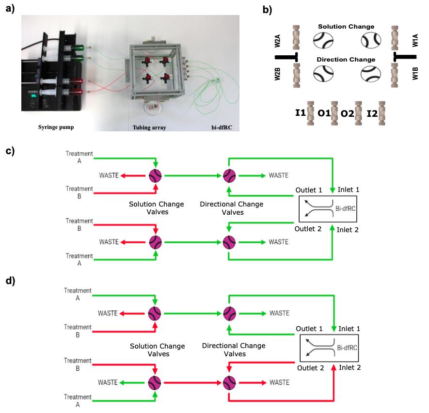
Figure 5. Tubing array set up for delivery of test solutions into the bi-dfRC observation channel. (a) Syringe pump and tubing array setup for delivery of test solutions into the bi-dfRC microchannels, harbouring solution and directional change valves. Set to deliver full treatment (green) through inlets A & B of the bi-dfRC at the differentiation zone. (b) Placement of all solution and directional change valves, waste (W) Low Pressure Unions (WIA-1B, W2A-2B) and Low Pressure Union inlets (I) 1-2 and outlets (O) 1-2 for delivery of test solutions into the bi-dfRC. (c) Schematic diagram depicting the delivery of a full treatment A (green) through inlets 1 and 2 of the bi-dfRC. (d) Schematic diagram depicting the delivery of an asymmetric one-sided treatment A (green) through inlet 1 and treatment B (red) through inlet 2 of the bi-dfRC. Rotating the solution change valves as desired will switch which treatment enters the bi-dfRC, allowing application of full or half treatments. Adjusting the directional change valves will switch what side of the bi-dfRC the treatment enters, changing inlets 1 and 2 to outlets.
Imaging
Using an epi-fluorescent microscope (or desired microscope), place the bi-dfRCs connected to the tubing array onto the microscope stage.
Focus on the sample with brightfield under a 5× lens (EC Plan-Neofluar 5×/0.15 M27).
Pre-wet/restore filling of the flow matrix.
Connect the syringe pump system equipped with the pre-solution-filled flow matrix to the bi-dfRC inlet/outlets.
Secure the bi-dfRC with tubing attached onto the microscope stage.
Note: For a known flow rate, refer to the following equation for the time it will take media to arrive at the bi-dfRC observation channel following solution change:
t=(πr2)d/Q
where t is the time, r is the tubing radius (internal), d is the tubing length, and Q is the flow rate.
Conduct the desired experiments.
Validation of protocol
Successful A. thaliana wild-type Col-0 and transgenic G-CaMP3 plant culture and root growth into the bi-dfRC microchannel was replicated under PVP-treated microchannels (Allan et al., 2023, Figure 1d). Successful culture of wild-type N. benthamiana and S. lycopersicum was shown in this protocol (Figure 4a–4c). Bi-dfRC molds can be supplied as part of a collaboration or contract work (please contact
General notes and troubleshooting
Troubleshooting
If sub-optimal bonding of the bi-dfRCs occurs between the polydimethylsiloxane substrate and glass slide base, pre-wet the inside of the plasma cleaner chamber with deionized water to increase humidity and/or run a pre-clean cycle firstly at 100 W power, pulse ratio of 255, and 5 sccm of oxygen for 15 min (nitrogen clean), secondly at 100 W power, pulse ratio of 255, and 5 sccm of oxygen for 10 min (clean), and lastly at 15 W power, pulse ratio of 50, and 5 sccm of oxygen for 1 min (polydimethylsiloxane bond cycle).
If the bi-dfRCs are contaminated during plant incubation on chip, pre-sterilise the bi-dfRCs in an autoclave at 121 °C for 1 h, using heat safe containers.
To further control for uneven asymmetric flow in the bi-dfRC microchannel, ensure that all valves and fittings are tight, and tubing is connected securely to the bi-dfRC inlets/outlets with no tears in the polydimethylsiloxane.
Acknowledgments
The authors thank Linda Chen for help with epoxy dye treatment and Gary Turner for fabrication of the raised mount to secure the tubing array. C. Allan is recipient of a PhD scholarship from the Biomolecular Interaction Centre, Christchurch. B. Elliot holds a MSc scholarship from The Brian Mason Scientific & Technical Trust. Further funding was provided to C. Meisrimler by the Department of Science, University of Canterbury and Royal Society Te Apārangi Catalyst funding CSG-UOC1902, and to V. Nock by Rutherford Discovery Fellowship RDF-19-UOC-019 and the Biomolecular Interaction Centre, University of Canterbury. The protocol has been derived from Allan et al. (2023).
Competing interests
The authors declare that they have no conflict of interest.
References
- Allan, C., Tayagui, A., Nock, V. and Meisrimler, C. N. (2022). Novel Bi-Directional Dual-Flow-Rootchip to Study Effects of Osmotic Stress On Calcium Signalling in Arabidopsis Roots. In: 2022 IEEE 35th International Conference on Micro Electro Mechanical Systems Conference (MEMS) (pp. 896–899). IEEE, Tokyo.
- Allan, C., Tayagui, A., Hornung, R., Nock, V. and Meisrimler, C. N. (2023). A dual-flow RootChip enables quantification of bi-directional calcium signaling in primary roots. Front. Plant Sci. 13: e1040117.
- Data Sheets/Research Papers. (2020). Retrieved 3 October 2022, from https://djmicrolaminates.com/wp-content/uploads/2020/06/Thick-SUEX-Data-Sheet-June-2020.pdf
- Data Sheets/Research Papers. (2021). Retrieved 20 February 2021, from https://djmicrolaminates.com/resources/white-papers-research-papers/
- Farooq, M., Hussain, M., Wahid, A. and Siddique, K. H. M. (2012). Drought Stress in Plants: An Overview. In: Aroca, R. (Ed.). Plant Responses to Drought Stress (pp. 1–33). Springer, Berlin.
- Freschi, L. (2013). Nitric oxide and phytohormone interactions: current status and perspectives. Front. Plant Sci. 4: e00398.
- Kitson, P. J., Rosnes, M. H., Sans, V., Dragone, V. and Cronin, L. (2012). Configurable 3D-Printed millifluidic and microfluidic ‘lab on a chip’ reactionware devices. Lab Chip 12(18): 3267.
- Lamers, J., van der Meer, T. and Testerink, C. (2020). How Plants Sense and Respond to Stressful Environments. Plant Physiol. 182(4): 1624–1635.
- Nazarov, P. A., Baleev, D. N., Ivanova, M. I., Sokolova, L. M. and Karakozova, M. V. (2020). Infectious plant diseases: etiology, current status, problems and prospects in plant protection. Acta Naturae 12(3): 46–59.
- Nejat, N. and Mantri, N. (2017). Plant Immune System: Crosstalk Between Responses to Biotic and Abiotic Stresses the Missing Link in Understanding Plant Defence. Curr. Issues Mol. Biol. 23: 1–16.
- Noman, M., Aysha, J., Ketehouli, T., Yang, J., Du, L., Wang, F. and Li, H. (2021). Calmodulin binding transcription activators: An interplay between calcium signalling and plant stress tolerance. J. Plant Physiol. 256: 153327.
- Stanley, C. E., Shrivastava, J., Brugman, R., Heinzelmann, E., Frajs, V., Bühler, A., van Swaay, D. and Grossmann, G. (2018a). Fabrication and Use of the Dual-Flow-RootChip for the Imaging of Arabidopsis Roots in Asymmetric Microenvironments. Bio Protoc 8(18): e3010.
- Stanley, C. E., Shrivastava, J., Brugman, R., Heinzelmann, E., van Swaay, D. and Grossmann, G. (2018b). Dual-flow-RootChip reveals local adaptations of roots towards environmental asymmetry at the physiological and genetic levels. New Phytol. 217(3): 1357–1369.
- Soffe, R., Mach, A. J., Onal, S., Nock, V., Lee, L. P. and Nevill, J. T. (2020). Art‐on‐a‐Chip: Preserving Microfluidic Chips for Visualization and Permanent Display. Small 16(34): 2002035.
- Sewelam, N., Kazan, K. and Schenk, P. M. (2016). Global Plant Stress Signaling: Reactive Oxygen Species at the Cross-Road. Front. Plant Sci. 7: e00187.
- Toyota, M., Spencer, D., Sawai-Toyota, S., Jiaqi, W., Zhang, T., Koo, A. J., Howe, G. A. and Gilroy, S. (2018). Glutamate triggers long-distance, calcium-based plant defense signaling. Science 361(6407): 1112–1115.
Supplementary information
The following supporting information can be downloaded here:
- Supplemental File 1. Design for A. thaliana bi-dfRC in Mentor Graphics, exported as a dxf file
- Supplemental File 2. Design for N. benthamiana bi-dfRC in Mentor Graphics, exported as a dxf file
- Supplemental File 3. Design for S. lycopersicum bi-dfRC in Mentor Graphics, exported as a dxf file
Article Information
Copyright
© 2023 The Author(s); This is an open access article under the CC BY-NC license (https://creativecommons.org/licenses/by-nc/4.0/).
How to cite
Allan, C., Elliot, B., Nock, V. and Meisrimler, C. N. (2023). Bi-directional Dual-flow-RootChip for Physiological Analysis of Plant Primary Roots Under Asymmetric Perfusion of Stress Treatments. Bio-protocol 13(15): e4764. DOI: 10.21769/BioProtoc.4764.
Category
Plant Science > Plant physiology > Plant growth
Cell Biology > Cell imaging > Microfluidics
Biological Sciences > Biological techniques
Do you have any questions about this protocol?
Post your question to gather feedback from the community. We will also invite the authors of this article to respond.