- Protocols

- Articles and Issues
- For Authors
- About
- Become a Reviewer

An Improved System to Measure Leaf Gas Exchange on Adaxial and Abaxial Surfaces
Published: Vol 13, Iss 11, Jun 5, 2023 DOI: 10.21769/BioProtoc.4687 Views: 1489
Reviewed by: Ansul LokdarshiRaviraj Mahadeo KalunkeAnonymous reviewer(s)
Original research article
The authors used this protocol in:
Mar 2021
Advertisement


Protocol Collections
Comprehensive collections of detailed, peer-reviewed protocols focusing on specific topics


Abstract
Measurement of leaf carbon gain and water loss (gas exchange) in planta is a standard procedure in plant science research for attempting to understand physiological traits related to water use and photosynthesis. Leaves carry out gas exchange through the upper (adaxial) and lower (abaxial) surfaces at different magnitudes, depending on the stomatal density, stomatal aperture, cuticular permeability, etc., of each surface, which we account for in gas exchange parameters such as stomatal conductance. Most commercial devices measure leaf gas exchange by combining the adaxial and abaxial fluxes and calculating bulk gas exchange parameters, missing details of the plant's physiological response on each side. Additionally, the widely used equations to estimate gas exchange parameters neglect the contribution of small fluxes such as cuticular conductance, adding extra uncertainties to measurements performed in water-stress or low-light conditions. Accounting for the gas exchange fluxes from each side of the leaf allows us to better describe plants' physiological traits under different environmental conditions and account for genetic variability. Here, apparatus and materials are presented for adapting two LI-6800 Portable Photosynthesis Systems to work as one gas exchange system to measure adaxial and abaxial gas exchange simultaneously. The modification includes a template script with the equations to account for small fluxes. Instructions are provided for incorporating the add-on script into the device's computational sequence, display, variables, and spreadsheet results. We explain the method to obtain an equation to estimate boundary layer conductance to water for the new setup and how to embed this equation in the devices' calculations using the provided add-on script. The apparatus, methods, and protocols presented here provide a simple adaptation combining two LI-6800s to obtain an improved system to measure leaf gas exchange on adaxial and abaxial surfaces.
Graphical overview

Figure 1. Diagram of the connection of two LI-6800s. Figure adapted from Márquez et al. (2021).
Background
For simplicity, most common commercial gas exchange devices mix gases from the upper and lower cuvettes to estimate bulk gas exchange parameters from the mix. However, in some cases, it is desirable to analyse the characteristics of the leaf gas exchange on each leaf surface independently, such as when analysing adaxial and abaxial cuticular permeability in planta (Márquez et al., 2022), the stomatal contribution to the gas exchange of each surface (Wall et al., 2022), the estimation of water vapour (Wong et al., 2022) and CO2 (Márquez et al., 2023) gradients within the leaf, etc.
It has been common to use elaborate in-house built gas exchange systems to measure adaxial and abaxial gas exchange independently [see Jarvis and Slatyer (1966), Jones and Slatyer (1972) and Wong et al. (1985)]; however, it requires proficiency in electronics calibration, sensor tuning, environmental conditions control, and expertise in designing the tubing and manifolds. The LI-6800 incorporates automatic calibration protocols, well-tuned sensors, and its design permits modifying the chamber without major interference with the other parts of the system, allowing us to easily conjoin two instruments to analyse the adaxial and abaxial surfaces of a leaf.
The chamber modification demands re-measuring the boundary layer conductance to water for each cuvette to be accounted for in the computation of the gas exchange parameters. In this protocol, we walk the reader through the process of mounting the two LI-6800s together and measuring the boundary layer conductance following a method adapted from Parkinson (1985) to be used in LI-6800 devices. We provide an add-on script for the LI-6800 to include the new boundary layer conductance estimations for each cuvette in the calculations. The add-on script also includes an update to the latest theory for estimating gas exchange parameters presented by Márquez et al. (2021), which is a more precise physical approach to the electrical resistance analogy for gas exchange. The new boundary layer conductance and equations are included in the instrument's computation, display, variables, and spreadsheet results using the add-on code.
Materials and reagents
Joining two LI-6800
Two cuvette flanges (in-house designed, schematics in Supplement 1)
Lower chamber lid (in-house designed, schematics in Supplement 2)
Sealed top chamber lid (in-house designed)
Note: Sealed top lid design is similar to the lower chamber lid design except for the thermocouple holder apertures. The sealed top chamber lid does not have thermocouple holder apertures.
Sealed flange (in-house designed, schematics in Supplement 3)
Flexible stainless-steel tube, 12 mm diameter
O-rings and screws according to the schematics
Thermocouple extension cable with 3.5 mm Jack connectors
(Recommended) LI-6800 Custom Chambers Manifold (LI-COR, catalog number: 6800-19)
Bev-A-line IV tube
Before taking measurements
Polycarbonate sheet 2–3 mm thick, big enough to cover the surface of the chamber and seals
Boundary layer conductance estimation
Glass microfibre filters GF/A 9 cm (Whatman, catalog number: WHA1820090)
PEEK tube Orange 1/16 × 0.02 (IDEX, catalog number: 1532)
250 mL glass beaker
Pure water (reverse osmosis or distilled)
Equipment
Two photosynthesis systems LI-6800 (LI-COR Biosciences, Lincoln, Nebraska)
Software
Add-on script for LI-6800 to use double chamber (in-house coded, download from: https://github.com/PlantPhysiologist/MSF_UpperLower)
Procedure
Joining two LI-6800
Connect the flanges and tubing as shown in Figure 1 and 2. The upper and lower jaws holding the cuvettes should remain connected to LI-6800 #1 so that the lever for opening and closing the chamber remains operational. Place the thermocouple from the LI-6800 #1 to touch the leaf and position #2 to measure the air temperature of the lower cuvette. Keep the light of the LI-6800 #2 switched off to avoid extra heat in the system.
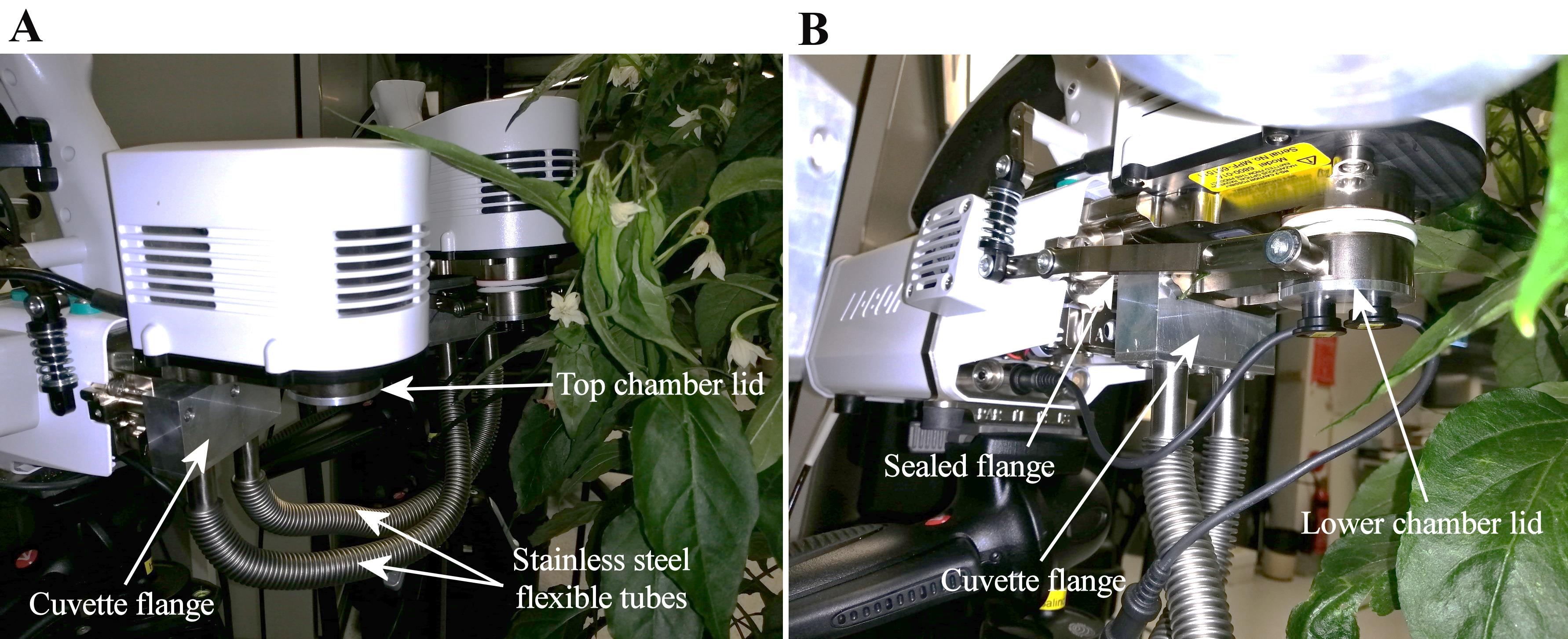
Figure 2. Flanges- and tubing-connected LI-6800 #1 (A) and #2 (B)
Alternatively, reference and sample gases from LI-6800 #2 (Figure 3) can be separated using a Custom Chambers Manifold from LI-COR (part number 6800-19, not included when buying an LI-6800), and then connecting the mixing volume and the reference gas in one tube going to the chamber and leaving the second tube connected to the sample gas inlet only. This last setup is recommended, though it is not used in Márquez et al. (2021) as it was developed after publication.
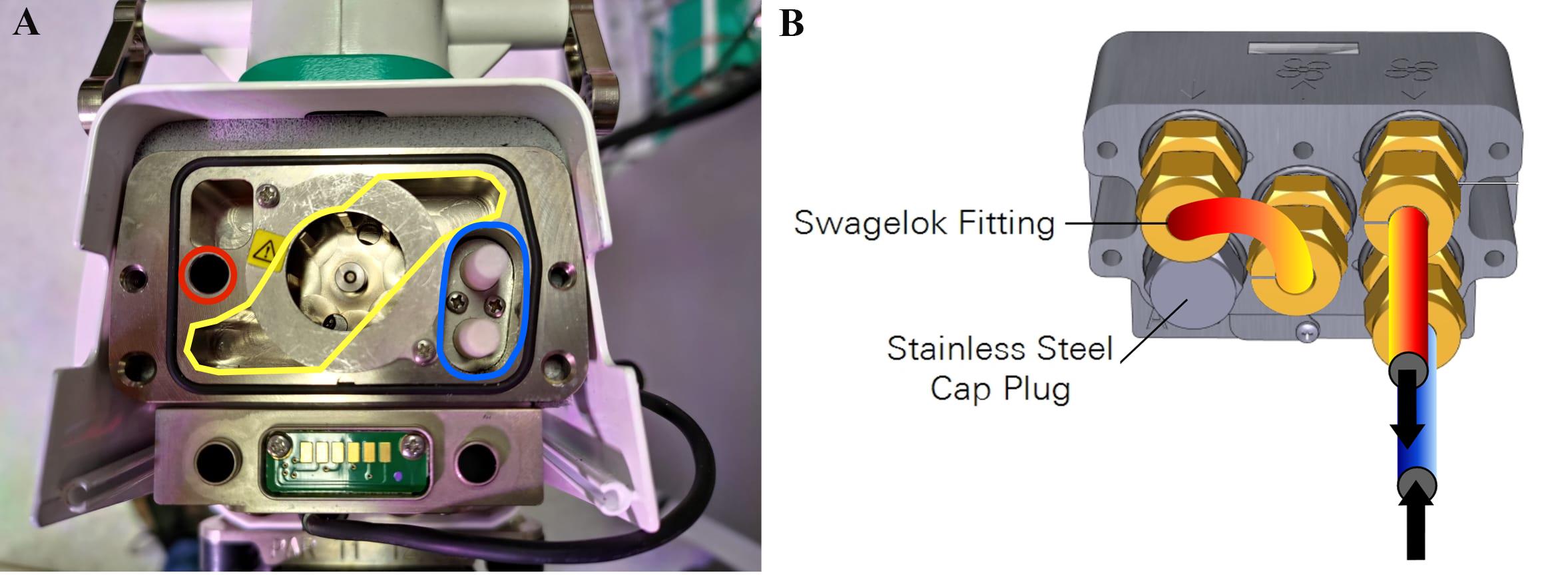
Figure 3. LI-6800 manifold in the head of the LI-6800 (A) and the connection for the Custom Chambers Manifold (B). Reference gas output (red), sample gas inlet (blue), and mixing fan volume (yellow). Connections are Bev-A-line IV tubes. Output and input tubing from the Custom Chamber Manifold are connected to Flexible stainless-steel tubes of 12 mm diameter.
Before taking measurements
Installing/loading the add-on script
Using a thumb drive or the Ethernet port, copy the add-on script file to the folder config.
Load the configuration Double cuvette from the display of your LI-6800 in the tab Startup/Configuration.
Warming up the instruments
As usual when using an LI-6800, put new chemicals in the water and CO2 scrub cylinders, refill the water in the humidifier, and install a new CO2 cartridge.
Turn off the light on both LI-6800s.
Place the polycarbonate sheet to isolate the gas from each cuvette and close the chamber.
Check for leaks by blowing CO2 (breath is a suitable mix) around the chamber and connections while checking the CO2 readings (they should not change).
Note: Correct any leak before continuing with measurements or warm up.
Run the automatic warm up of the instrument as usual.
Remove the polycarbonate sheet.
Boundary layer conductance estimation
Prepare the evaporative surface (Figure 4)
Fill the beaker with distilled water and submerge one end of the PEEK tube in it.
Suck through the PEEK tube to fill it with water.
Damp two microfibre filter sheets.
Put the PEEK tube between the two damped microfibre filter sheets.
Place the filter in the LI-6800 chamber and close it (the tube must sit in the middle of the chamber between the filters).
Place the beaker such that the water surface is a few centimetres higher than the filters, creating a siphon link, and taking care not to overflow the filter paper.
Ensure that the thermocouple in LI-6800 #1 is touching the microfibre filter and that #2 is not touching it.
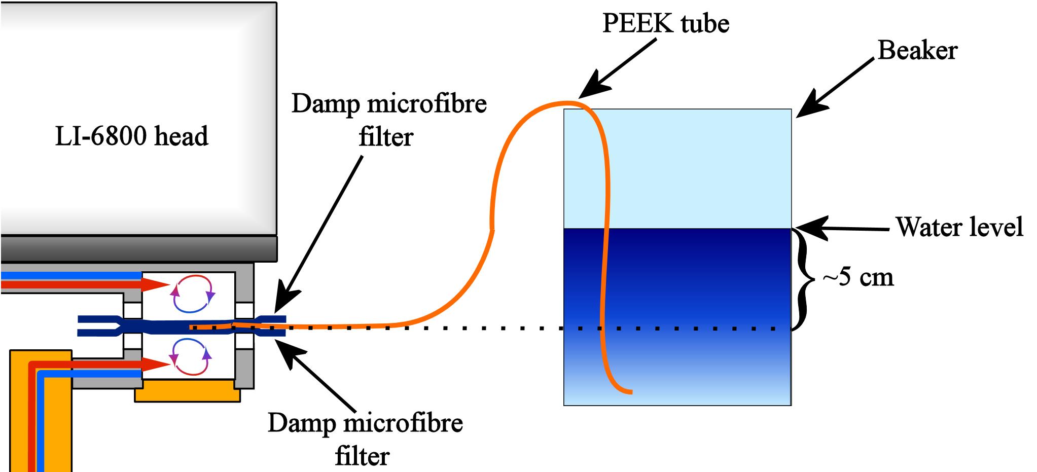
Figure 4. Schematic of the setup to measure boundary layer conductance
Measuring boundary layer conductance at different fan speeds
Set the parameters:
Both LI-6800s to a flow rate of 600 μmol s-1; sample CO2 concentration at 400 μmol mol-1; and lights off.
LI-6800 #1 to an air temperature of 25 °C and air saturation deficit (ASD) at 1.2 kPa.
LI-6800 #2 to a leaf temperature (thermocouple) of 25 °C and vapour pressure difference (VPD) at 1.2 kPa.
Take measurements from both cuvettes varying the fan revolutions (rpm) from 5,000 up to 13,000 rpm in steps of 1,000 rpm (Figure 5).
Note: The flow rate also affects the estimated boundary layer conductance, but it is usually a minor effect for the measurements taken with an LI-6800.
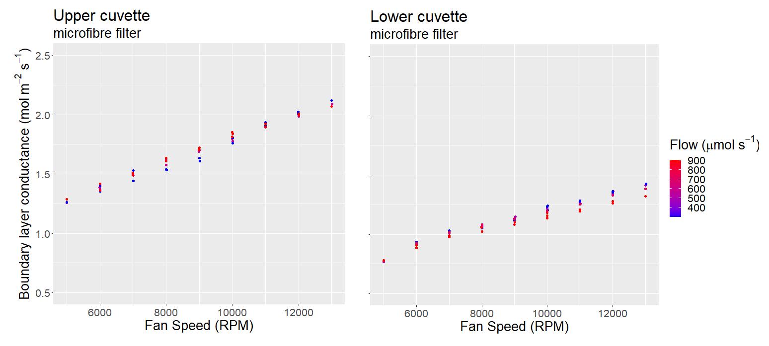
Figure 5. Measurements of boundary layer conductance
Taking measurements
Placing a leaf in the chamber
The leaf must cover the whole area of the chamber.
Verify that only the thermocouple from LI-6800 #1 is touching the leaf.
Set the overpressure in both LI-6800s to 0.1 kPa. Always keep the same overpressure in both cuvettes to avoid mass flow across the leaf.
Start the protocol for your measurements and open a file to save your data.
Data analysis
Data analysis and adding the new boundary layer estimation to the LI-6800s
Extract the Excel log files from both LI-6800s.
In the data file from LI-6800 #2, replace the values given for leaf temperature with those given in the file from LI-6800 #1.
Calculate the boundary layer conductance to water (gbw).
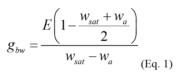
where E is transpiration, wsat is vapour saturation mole fraction at filter temperature, and wa is water content in the cuvette air. Note that this is identical to the equation for total conductance (gtw) in the LI-6800 results spreadsheet.
Extract the gbw data and fit a quadratic equation (gbw = ax2 + bx + c) using fan speed per thousand (rpm/1,000) as the x input.
Polynomial of second order trendline from Excel is a suitable tool to fit the equation.
We use fan speed per thousand in the equation to adjust a, b, and c to four significant figures in the script.
Using the LI-6800 display, insert the values for the variables a, b, and c in the tab Constants/User.
If the tubing and manifolds in the connections are not modified, the equation for estimating gbw does not need to be recalculated.
Post-processing data
Replace the Tair values with the Tleaf from the LI-6800 #2 spreadsheet, and the Tleaf values of the #2 spreadsheet for those in #1. The new calculations included by the add-on will appear clustered in the first columns of the results spreadsheet but will not replace the normal ones. Thus, the user should be careful not to mix the data when retrieving it.
Notes
Work with flow rates of 500 μmol s-1 or higher on each LI-6800 when possible.
Set the same overpressure on both LI-6800s to avoid mass flow across the leaf.
The PEEK tube may be replaced by a piece of microfibre filter with one end in the beaker and the other between the two microfibre filters, but take extra precautions to prevent the microfibre outside the chamber from drying during the measurements.
Set the same air temperature on both cuvettes to keep the cuvette condition identical when modifying water parameters (notice that the thermocouple is measuring the air temperature in LI-6800 #2).
Acknowledgments
We thank P. Groeneveld for technical support and building the LI-6800 connector. We also thank ANID Doctorado, Becas Chile/2015 Folio 72160160 for funding part of the research and ARC support in the form of a Discovery Grant (no. DP210103186). The method here adapted was first published in Márquez et al. (2021) Nature Plants DOI: 10.1038/s41477-021-00861-w.
Competing interests
The authors declare no competing interests.
References
- Jarvis, P. G. and Slatyer, R. O. (1966). A controlled-environment chamber for studies of gas exchange by each surface of a leaf. Commonwealth Scientific and Industrial Research Organization.
- Jones, H. G and Slatyer, R. O. (1972). Effects of intercellular resistances on estimates of the intracellular resistance to CO2 uptake by plant leaves. Aust J Biol Sci 25(3): 443-454.
- Márquez, D. A., Stuart-Williams, H., Cernusak, L. A. and Farquhar, G. D. (2023). Assessing the CO2 concentration at the surface of photosynthetic mesophyll cells. New Phytol. doi: 10.1111/nph.18784. Online ahead of print.
- Márquez, D. A., Stuart-Williams, H. and Farquhar, G. D. (2021). An improved theory for calculating leaf gas exchange more precisely accounting for small fluxes. Nat Plants 7(3): 317-326.
- Márquez, D. A., Stuart-Williams, H., Farquhar, G. D. and Busch, F. A. (2022). Cuticular conductance of adaxial and abaxial leaf surfaces and its relation to minimum leaf surface conductance. New Phytol 233(1): 156-168.
- Parkinson, K. J. 1985. A simple method for determining the boundary layer resistance in leaf cuvettes. Plant Cell Environ 8(3): 223-226.
- Wall, S., Vialet-Chabrand, S., Davey, P., Van Rie, J., Galle, A., Cockram, J. and Lawson, T. (2022). Stomata on the abaxial and adaxial leaf surfaces contribute differently to leaf gas exchange and photosynthesis in wheat. New Phytol 235(5): 1743-1756.
- Wong, S. C., Canny, M. J., Holloway-Phillips, M., Stuart-Williams, H., Cernusak, L. A., Marquez, D. A. and Farquhar, G. D. (2022). Humidity gradients in the air spaces of leaves. Nat Plants 8(8): 971-978.
- Wong, S. C., Cowan, I. R. and Farquhar, G. D. (1985). Leaf Conductance in Relation to Rate of CO(2) Assimilation: II. Effects of Short-Term Exposures to Different Photon Flux Densities. Plant Physiol 78(4): 826-829.
Article Information
Copyright
© 2023 The Author(s); This is an open access article under the CC BY-NC license (https://creativecommons.org/licenses/by-nc/4.0/).
How to cite
Márquez, D. A., Stuart-Williams, H., Wong, S. C. and Farquhar, G. D. (2023). An Improved System to Measure Leaf Gas Exchange on Adaxial and Abaxial Surfaces. Bio-protocol 13(11): e4687. DOI: 10.21769/BioProtoc.4687.
Category
Plant Science > Plant physiology
Do you have any questions about this protocol?
Post your question to gather feedback from the community. We will also invite the authors of this article to respond.