- Protocols

- Articles and Issues
- For Authors
- About
- Become a Reviewer

Single Protein Detection and Imaging with Evanescent Scattering Microscopy
(*contributed equally to this work) Published: Vol 12, Iss 20, Oct 20, 2022 DOI: 10.21769/BioProtoc.4530 Views: 1892
Reviewed by: Zinan ZhouAli Asghar KermaniArif Md. Rashedul Kabir
Original research article
The authors used this protocol in:

Apr 2022
Advertisement


Protocol Collections
Comprehensive collections of detailed, peer-reviewed protocols focusing on specific topics


Related protocols
Abstract
Single-molecule measurements provide statistical distributions of molecular properties, in addition to the ensemble averages. Evanescent detection approaches have been widely used for single-molecule detection because the evanescent field can significantly enhance the light-analyte interaction and reduce the background noise. However, current evanescent single-molecule detection systems mostly require specially designed sensing components. Here, we show that single proteins can be imaged on a plain cover glass surface by detecting the evanescent waves scattered by the target molecules. This allows us to quantify the protein–antibody interactions at the single-molecule level. This protocol describes a label-free single-molecule imaging approach with conventional consumables and may pave the road for detecting single molecules with commercial optical microscopy.
Keywords: Single-molecule imagingBackground
Label-free single-molecule imaging allows the statistical analysis of intrinsic molecular properties such as size, mass, and binding kinetics. Evanescent field can notably increase the light-analyte interaction and suppress the background light by reducing the illumination volume. Traditional evanescent detection approaches, such as surface plasmon resonance (SPR), usually measure the ensemble properties of analytes diffusing into the evanescent field by monitoring the variations of incident light exciting the evanescent field (Homola, 2008; Zhang et al., 2018). In recent years, it has been demonstrated that directly measuring the evanescent waves scattered by the analytes can significantly improve the detection sensitivity and even push the detection limit down to the single-molecule level (Mauranyapin et al., 2017). Plasmonic scattering microscopy (PSM) has further advanced this field by providing wide-field single-molecule imaging capabilities (Zhang et al., 2020). However, PSM employs the surface plasmonic field as the illumination, and the gold film supporting the plasmonic field will generate massive heat at high-incident light intensity, which is required to achieve enough signal-to-noise ratio for single-molecule detection. This thus limits its application in the detection of fragile biological macromolecules, as well as long-term monitoring of molecular binding processes (Zhang et al., 2021).
To further push the evanescent scattering detection approaches forward, we recently developed the evanescent scattering microscopy (ESM), which can perform label-free evanescent scattering imaging of single proteins on plain cover glass surfaces (Zhang et al., 2022). The ESM utilizes total internal reflection to replace the surface plasmon resonance to excite the evanescent field, thus avoiding the heating effect by removing the gold film, and making it suitable for detecting most molecules with conventional consumables. In the following protocol, we describe in detail the construction of an ESM system with commercially available components and its single-molecule imaging operations.
Materials and Reagents
Syringe (BD, catalog number: 302830) with needle (Weller, catalog number: KDS2312P) with the flexible plastic tubing (Tygon, catalog number: AAD04103)
Microfluidic ball valves (Cole-Parmer, catalog number: EW-30600-00)
Cover glasses No. 1, 22 × 22 mm (VWR, catalog number: 48366-067)
Cover glasses No. 1, 18 × 18 mm (VWR, catalog number: 48366-045)
Petri dish (Sigma-Aldrich, catalog number: P5731)
0.22 µm filter (Sigma-Aldrich, catalog number: SLGSM33SS)
Isopropyl alcohol (IPA, VWR, catalog number: BDH2032-1GLP)
Hydrogen peroxide (H2O2, 30%) (Sigma-Aldrich, catalog number: H1009)
(3-aminopropyl) triethoxysilane (APTES) (Sigma-Aldrich, catalog number: 440140)
Succinic anhydride (Sigma-Aldrich, catalog number: 239690)
Bovine serum albumin (BSA) (Sigma-Aldrich, catalog number: A7638)
Sodium hydroxide (NaOH) (Sigma-Aldrich, catalog number: S5881)
Ammonium hydroxide (NH3·H2O, 28.0%–30.0%) (Mallinckrodt Reagents, catalog number: C5103500-2.5D)
1-ethyl-3-(3-dimethylaminopropyl)carbodiimide hydrochloride (EDC) (Thermo Scientific, catalog number: 22980)
Sulfo-NHS (N-hydroxysulfosuccinimide) (Thermo Scientific, catalog number: 24510)
Phosphate-buffered saline (PBS) (Corning, catalog number: 21-040-CV)
Anti-IgA (IgG) (Bio-Rad, catalog number: STAR141)
Human colostrum IgA (Athens Research and Technology, catalog number: 16-13-090701)
Human IgM (Athens Research and Technology, catalog number: 16-16-090713)
Office tape (3MTM ScotchTM, 810, 3/4 in × 108 ft, 1 in Tape Core Dia, Transparent, Matte)
10 g L−1 succinic anhydride (see Recipes)
NH3·H2O, H2O2, and water (see Recipes)
EDC–NHS solution (see Recipes)
Equipment
Optical breadboard (Newport, model: SG-23-4-ML)
Active vibration isolation stage (Accurion, model: Vario Basic 60-300)
80 mW laser diode (Thorlabs, model: PL450B)
Temperature-controlled mount (Thorlabs, model: LDM38)
Benchtop diode current controller (Thorlabs, model: LDC205C)
Temperature controller (Thorlabs, model: TED200C)
Manual translation stage (Thorlabs, model: XR25P-K2)
Posts and Accessories essentials kit (Thorlabs, model: ESK16)
Bases and Post Holders essentials kit (Thorlabs, model: ESK01)
SM1 Lens Tube essentials kit (Thorlabs, model: ESK25)
Ø 2" Optic Mounts essentials kit (Thorlabs, model: ESK19)
Pillar Post essentials kit (Thorlabs, model: ESK15)
Lens Mount essentials kit (Thorlabs, model: ESK22)
C-Mount Extension Tube kit (Thorlabs, model: CML-KIT)
SM2 Lens Tube essentials kit (Thorlabs, model: ESK26)
Cage Assemblies and Lens Tubes essentials kit (Thorlabs, model: ESK07A)
Cage Assemblies and Lens Tubes essentials kit Set B (Thorlabs, model: ESK07B)
Mounted Ø 1" Achromatic Lens kit (Thorlabs, model: LSB08-A)
Cage cube–mounted protected silver turning mirror (Thorlabs, model: CCM1-P01)
Camera (XIMEA, model: MQ003MG-CM and MQ013MG-CM)
25 mm × 36 mm protected silver mirror (Thorlabs, model: PFR10-P01)
Kinematic fluorescence filter cube (Thorlabs, model: DFM1)
SM1A2 adapter (Thorlabs, model: SM1A2)
60 mm cage system translating lens mount (Thorlabs, model: CXY2)
Brass microscope adapter (Thorlabs, model: M2M34S)
Cage plate (Thorlabs, model: LCP08)
Thermally insulating adapter (Thorlabs, model: SM1A3TS)
Zoom housing (Thorlabs, model: SM1ZM)
Reflective ND filter (Thorlabs, model: ND40A)
30–60 mm cage plate adapter (Thorlabs, model: LCP33)
Cage assembly rods (Thorlabs, model: ER18)
Plate (Thorlabs, model: CPVMP)
Kinematic beam-turning cage cube (Thorlabs, model: DFM1-P01)
Dovetail optical rail (Thorlabs, model: RLA1800)
60× objective (Olympus APO N 60× Oil TIRF, NA 1.49)
50× objective (Motic ULWD 50×, NA 0.42)
Achromatic doublet lens (Thorlabs, model: AC508-180-A-ML, AC254-100-AB-ML, and AC254-030-AB-ML)
Ø 1.5" Posts (Thorlabs, model: P6, P8, P10, P12, P14)
Robbins biopsy punch (Robbins Instruments, catalog number: 18271P)
Sylgard 184 silicone elastomer (Dow Silicones Corporation, catalog number: 04019862)
Potomac laser (1450 South Rolling Road Baltimore MD, 21227, USA)
BD-20AC laboratory corona treater (Electro-Technic Products, catalog number: 12051A)
Oven (Thermo Scientific, model: PR305225M)
Double-coated tape (3M, catalog number: 9628B)
Devcon epoxy (Euro Tool, catalog number: GLU-735.90)
Software
XIMEA CamTool (XIMEA)
MATLAB (MathWorks)
Fiji (https://imagej.net/Fiji)
Origin 2019 (OriginLab)
Office 365 (Microsoft)
Procedure
Setting the optical arrangement
Put the optical breadboard onto an active vibration isolation stage.
Arrange the optical components in the order shown in Figure 1. The details for each component are listed below. All components are fixed onto the breadboard with TR075 or TR1 optical posts (Posts and Accessories essentials kit), and PH1 or PH1.5 post holders and BA1 mounting bases (Bases and Post Holders essentials kit), depending on their sizes.
An 80 mW laser diode is fixed at a temperature-controlled mount as the light source. The laser diode is driven by a benchtop diode current controller and a temperature controller. The mount is fixed onto the breadboard with two TR075 optical posts and two PH1 post holders. The post holders are fixed on the breadboard using a ¼”–20 × ½” screw set.
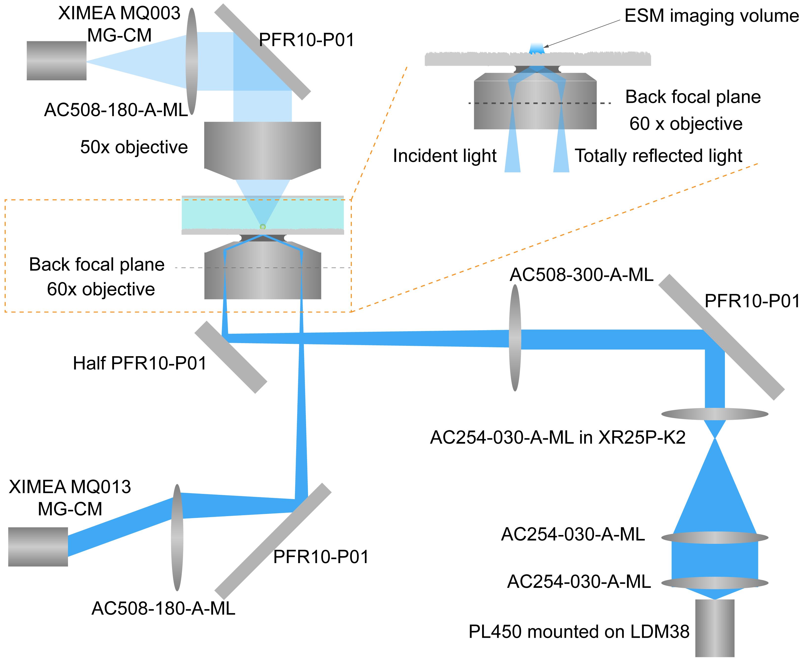
Figure 1. Optical arrangement of the ESM. Light from the laser diode is conditioned by an achromatic doublet lens group and then focused on the back focal plane of a 60× objective by a tube lens. The incident angle is adjusted by a manual translation stage to reach total internal reflection condition at 65°. Reflection light is also collected by a camera to help finding the objective focus position. Scattered light from the protein and glass surface is collected by a 50× objective to form an ESM image by a second camera.Fix one SM1L20C slotted lens tube (SM1 Lens Tube essentials kit) into the temperature-controlled mount. Put one AC254-030-A achromatic doublet lens (Mounted Ø 1” Achromatic Lens kit) into the slotted lens tube, and fix its position with two SM1 retaining rings to achieve collimation laser light.
Fix one AC254-100-A-ML achromatic doublet lens (Mounted Ø 1" Achromatic Lens kit) at the end of the slotted lens tube.
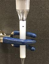
Fix one AC254-030-A-ML achromatic doublet lens (Mounted Ø 1" Achromatic Lens kit) with one SMR1 lens mount. Connect the lens mount to one TR3 optical post (Posts and Accessories essentials kit), and then fix it with another two TR3 optical posts and two RA90 right-angle post clamps (Posts and Accessories essentials kit) onto one XR25P-K2 manual translation stage. Figure 2A shows the picture of the assembled parts.
Fix one RLA1800 dovetail optical rail onto the breadboard with cap screws.
Fix one DFM1-P01 kinematic beam-turning cage cube onto the dovetail optical rail using one TR075 optical post, one PH1 post holder, and one RC2 dovetail rail carrier.
Fix one CPVMP plate with cap screws at the end of the dovetail optical rail.
Fix four ER18 cage assembly rods onto the CPVMP plate to construct the structure for one 60 mm vertical cage system.
Fix one LCP33 30–60 mm cage plate adapter onto the cage assembly rods.
Fix one cage cube–mounted protected silver turning mirror at the bottom of the cage plate adapter with four ER025 cage assembly rods.
Fix one AC508-180-A-ML achromatic doublet lens onto the turning mirror as the imaging tube lens with one SM1A2 adapter.
Fix one camera (MQ013MG-CM) equipped with one ND40A reflective ND filter at the focal point of the achromatic doublet lens to monitor the position of the reflection beam.
Fix one kinematic fluorescence filter cube at the top of the cage plate adapter with four ER025 cage assembly rods. One half reflector is set in the cube to allow the transmission of both incident and reflection beams. One half reflector (25 mm x 18 mm) is prepared by cutting the 25 mm x 36 mm protected silver mirror in two equal parts, which can be customized by the Thorlabs technique support team.
Fix another cage plate adapter onto the cage assembly rods at the top of the kinematic fluorescence filter cube. Fix one SM1ZM zoom housing onto the plate adaptor.
Fix one 60× objective onto the zoom housing with a Thorlabs SM1A3TS thermally insulating adapter.
Rotate and paste the office tape in the middle of the 60× objective to reach the final diameter of approximately 34 mm. Fix one LCP08 cage plate with one M2M34S brass microscope adapter onto the cage assembly rods. Ensure the tape circles attach to the adaptor surface to suppress the drift.
Fix one CXY2 60 mm cage system translating lens mount on the top of the objective to place the sensor chip.
Fix another CXY2 60 mm cage system translating lens mount onto the cage assembly rods and fix the SM2A6 adapter with external SM2 threads and internal SM1 threads onto the translating lens mount. Then, fix one SM1ZM zoom housing onto the adaptor.
Fix one 50× objective (working distance 20.5 mm) onto the zoom housing.
Fix another cage plate adapter onto the cage assembly rods. Fix one cage cube–mounted protected silver turning mirror onto the adaptor with four ER025 cage assembly rods.
Fix one AC508-180-A-ML achromatic doublet lens onto the turning mirror as the imaging tube lens with one SM1A2 adapter.
Fix one camera (MQ003MG-CM) at the focal point of the achromatic doublet lens to achieve the ESM image.
Preparing the sensor chip
Employ a 22 × 22 mm cover glass as the sensing substrate.
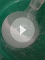
Clean the cover glasses in a boiling NH3·H2O, H2O2, and water solution for 1 h to obtain clean hydroxylated glass surfaces, where dropping water becomes a layer.
Wash the cover glasses and container twice with water, ultrasonically clean two times with water, and blow dry with nitrogen.
Incubate the hydroxylated cover glasses in boiling 1% APTES diluted with IPA for 3 h to functionalize the surface with the primary amine group. If drying in Step B2 was performed correctly, both the solution and cover glass should be clear after processing.
Wash the cover glass and container twice with IPA, ultrasonically clean twice with IPA, and blow dry with nitrogen.
Incubate the amino group–modified cover glasses in 10 g L−1 succinic anhydride for 1 h to obtain carboxylic group–functionalized cover glass chips. Adjust the pH of succinic anhydride solution to 7.5–8 with 1 M NaOH solution. Wash the cover glass and container twice with water, ultrasonically clean twice with water, and then store in water until use. Prior to the experiment, dry the cover glasses with nitrogen for fabricating the flow cell.
To fabricate the flow cell, prepare one 18 × 18 mm cover glass with two 1 mm holes, which can be drilled by laser.
Note: We asked the Potomac Laser for help to do this.
Use Sylgard 184 silicone elastomer to prepare the PDMS (Polydimethylsiloxane) plate with 3 mm thickness. Put 24 mL silicone elastomer solution into a Petri dish with 100 mm diameter, and then heat it at 60 °C in the oven to achieve a 3 mm thickness PDMS plate. Then, cut a PDMS part with 6 mm length, 3 mm width, and 3 mm thickness. Create a hole with approximately 1 mm at the middle of each PDMS part with the Robbins biopsy punch.
Use a laboratory corona treater to process the surfaces of the 18 × 18 mm cover glass and PDMS part. Then, attach the PDMS parts to the cover glass and place them into the oven at 90 °C for 1 h.
Use the knife to cut the double-coated tape into a small piece (18 × 18 mm) and create one channel (8 × 15 mm) in the middle of the tape piece. Attach the tape piece to the 22 × 22 mm cover glasses, and then attach the 18 × 18 mm cover glass with PDMS parts onto the tape piece. Seal the edges with Devcon epoxy. The final picture of the sensor chip is shown in Figure 2B.
Fix the sensor chip onto the CXY2 60 mm cage system translating lens mount with customized parts (Figure 2C).
Connect the sensor chip to one syringe with a needle with the flexible plastic tubing. On the sensor chip, 304 stainless steel capillary cubes can connect the tubing and PDMS part. The microfluidic ball valves are used to start and stop the waterflow. Place the syringe higher than the sensor chip and gravity will push the sample to flow onto the sensor surface.
In the experiment, the surface was incubated in 40 g L−1 EDC mixed with 11 g L−1 sulfo-NHS for 15 min to activate the carboxyl groups for connecting proteins. The EDC/NHS solution was filtered using a 0.22 µm filter before use.
Reinforcing the system structure
Apart from the lens fixed on the manual translation stage as shown in Figure 2A, all components should be connected with SM1 or SM2 optical tubes.
Use SM1TC or SM2TC clamps to fix each optical component by connecting it to another optical post fixed on the breadboard.
Connect the optical posts to each other with RA90 right-angle clamps and Ø 1/2" stainless steel optical posts (Figure 2D).
Data analysis
The raw image sequence captured at a high frame rate (approximately 200 fps) was converted to an averaged-image sequence, by averaging images over every 20 ms using the real-time averaging function of the camera recording software (XIMEA CamTool), to suppress shot noise. To remove the background, a differential image sequence was obtained by subtracting the previous frame from the present frame of the averaged-image sequence, using the Image Calculator plugin in Fiji. The TrackMate plugin in Fiji was employed to find and count molecules and achieve the ESM intensity of a molecule by averaging the powers of all pixels within the Airy disk. Following the operation instruction of TrackMate and selecting the “Export all spots statistics” at the final step, the mean intensity item is the result of averaging the powers of all pixels within the Airy disk. Origin 2019 was used to create data plots and histograms (Figure 3) and fit the histograms with Gaussian function using the Multiple Peak Fit tool.
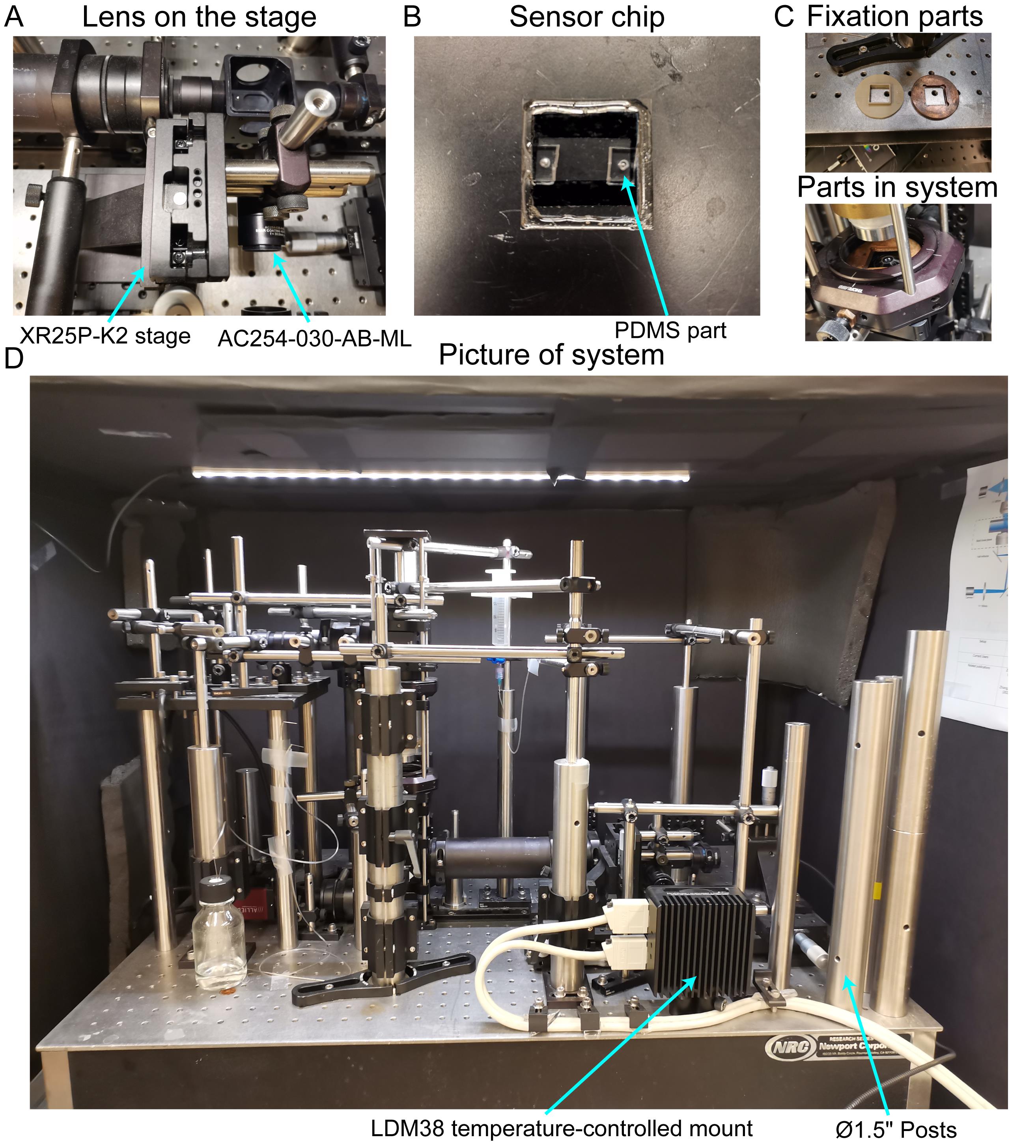
Figure 2. Picture of systems. (A) Lens on the manual translation stage. (B) Sensor chip. (C) Mechanical parts fixing the sensor chip onto the system. (D) Optical system.
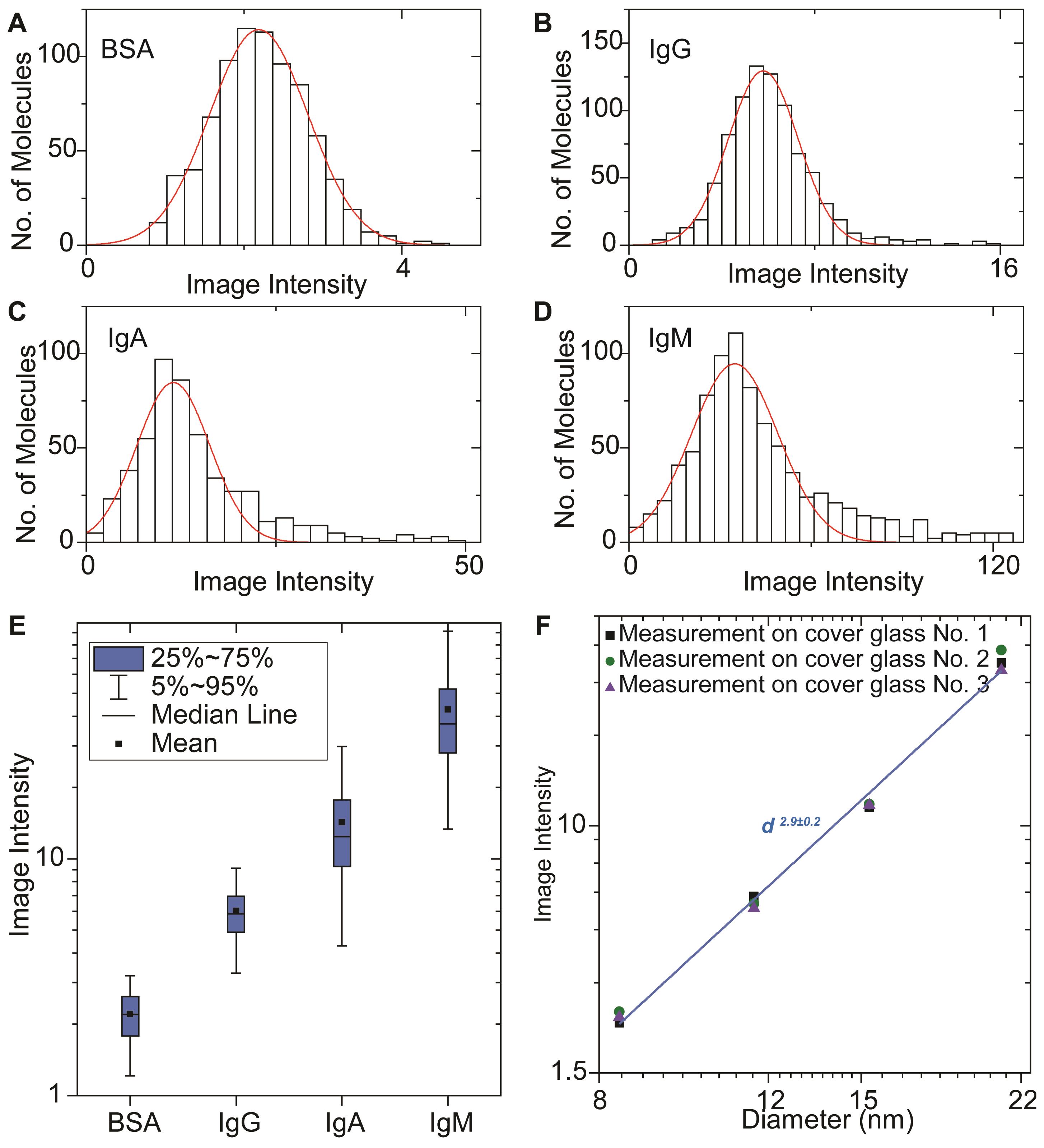
Figure 3. Image intensity histograms and calibration. Evanescent scattering microscopy image intensity histograms of BSA (A), IgG (B), IgA (C), and IgM (D) proteins, where the solid red curves are Gaussian fittings. (E) Box plots of image intensities measured on different proteins from A–D. (F) Evanescent scattering microscopy image intensity versus protein diameter, measured by dynamic light scattering in logarithmic scale.
Recipes
10 g L−1 succinic anhydride
Reagent Final concentration Amount Succinic anhydride 10 g L−1 n/a H2O n/a 100 mL Total n/a 100 mL NH3·H2O, H2O2, and water (volume ratio of 1:1:5)
Reagent Final concentration Amount NH3·H2O 15% 15 mL H2O2 15% 15 mL H2O
Total
70%
n/a
70 mL
100 mL
EDC–NHS solution
Reagent Final concentration Amount EDC 40 g L−1 n/a NHS
PBS buffer
11 g L−1
n/a
n/a
1 mL
Total n/a 1 mL
Acknowledgments
We thank the financial support from the National Institute of General Medical Sciences of the National Institutes of Health grant R01GM107165. This protocol was adapted from our previously published work (Zhang et al., 2022).
Competing interests
The authors declare no competing financial interest.
References
- Homola, J. (2008). Surface plasmon resonance sensors for detection of chemical and biological species. Chem Rev 108(2): 462-493.
- Mauranyapin, N. P., Madsen, L. S., Taylor, M. A., Waleed, M. and Bowen, W. P. (2017). Evanescent single-molecule biosensing with quantum-limited precision. Nature Photonics 11(8): 477-481.
- Zhang, P., Liu, L., He, Y., Chen, X., Ma, K., Wei, D., Wang, H. and Shao, Q. (2018). Composite layer based plasmon waveguide resonance for label-free biosensing with high figure of merit. Sensors and Actuators B: Chemical 272: 69-78.
- Zhang, P., Ma, G., Dong, W., Wan, Z., Wang, S. and Tao, N. (2020). Plasmonic scattering imaging of single proteins and binding kinetics. Nat Methods 17(10): 1010-1017.
- Zhang, P., Ma, G., Wan, Z. and Wang, S. (2021). Quantification of Single-Molecule Protein Binding Kinetics in Complex Media with Prism-Coupled Plasmonic Scattering Imaging. ACS Sens 6(3): 1357-1366.
- Zhang, P., Zhou, L., Wang, R., Zhou, X., Jiang, J., Wan, Z. and Wang, S. (2022). Evanescent scattering imaging of single protein binding kinetics and DNA conformation changes. Nat Commun 13(1): 2298.
Article Information
Copyright
© 2022 The Authors; exclusive licensee Bio-protocol LLC.
How to cite
Zhang, P., Zhou, L., Wang, R., Zhou, X., Jiang, J., Wan, Z. and Wang, S. (2022). Single Protein Detection and Imaging with Evanescent Scattering Microscopy. Bio-protocol 12(20): e4530. DOI: 10.21769/BioProtoc.4530.
Category
Biophysics > Single-molecule technique
Drug Discovery > Drug Screening
Biochemistry > Protein > Single-molecule Activity > Imaging
Do you have any questions about this protocol?
Post your question to gather feedback from the community. We will also invite the authors of this article to respond.