- Protocols

- Articles and Issues
- For Authors
- About
- Become a Reviewer

In vitro Fluid Shear Stress Induced Sclerostin Degradation and CaMKII Activation in Osteocytes
Published: Vol 11, Iss 23, Dec 5, 2021 DOI: 10.21769/BioProtoc.4251 Views: 2990
Reviewed by: Chiara AmbrogioSamuel RibeiroKarem A Court
Original research article
The authors used this protocol in:

Mar 2021

Protocol Collections
Comprehensive collections of detailed, peer-reviewed protocols focusing on specific topics


Related protocols
Abstract
Bone is a dynamic tissue that adapts to changes in its mechanical environment. Mechanical stimuli pressurize interstitial fluid in the lacunar-canalicular system within the bone matrix, causing fluid shear stress (FSS) across bone embedded, mechano-sensitive osteocytes. Therefore, modeling this mechanical stimulus in vitro is vital for identifying mechano-transduction cascades that contribute to the regulation of mechano-responsive proteins, such as the Wnt/β-catenin antagonist, sclerostin, which is reduced in response to FSS. Recently, we reported the rapid post-translational degradation of sclerostin protein in bone cells following FSS. Given the fundamental nature of sclerostin to bone physiology and the nuances of studying its rapid post-translational control, here, we detail our FSS protocol, and adaptations that can be made, to stimulate Ocy454 osteocyte-like cells to study sclerostin protein in vitro. While this protocol is optimized for detecting sclerostin degradation by western blot, this protocol can be adapted to examine transcriptional changes with RT-qPCR, cellular dynamics with live cell imaging, or secreted factors in the FSS buffer. This protocol utilizes 3D-printed FSS tips that are compatible with commercially available 96-well plates, allowing for high experimental accessibility, versatility, and throughput. However, this protocol can be adapted for any FSS chamber. It can also be combined with pharmacological inhibitors or genetic manipulations to interrogate the role of specific cellular components. In all, this experimental set-up and protocol is highly adaptable to allow for many experimental outcomes to examine many aspects of cell mechano-transduction.
Keywords: OsteocyteBackground
To withstand changes in its mechanical environment, bone must be able to sense and adapt to mechanical cues. Increases in mechanical strain lead to bone mass accrual and decreases in mechanical strain lead to bone mass loss. Osteocytes, bone-embedded cells that secrete many factors to regulate the activity of bone-forming osteoblasts and bone-resorbing osteoclasts, are mechano-sensitive and mediate bone mass changes in response to mechanical cues. One such factor osteocytes produce to regulate bone mass is the Wnt/β-catenin antagonist, sclerostin. Sclerostin inhibits osteoblast differentiation and function, halting bone formation (Winkler et al., 2003; Delgado-Calle et al., 2017). The application of mechanical stress to the skeleton causes the pressurization of interstitial fluid within the lacunar-canalicular system where the osteocytes reside. This pressurization causes fluid shear stress (FSS) across the osteocyte, acting as the mechanical stimulus that activates many mechano-transduction cascades. Osteocytes respond to FSS by reducing sclerostin protein abundance, lifting the inhibition on osteoblast differentiation to unleash load-induced bone formation (Robling et al., 2008; Tu et al., 2012; Lyons et al., 2017; Williams et al., 2020; Gould et al., 2021).
Modeling FSS in vitro is useful for identifying mechano-transduction cascades and molecular players that may contribute to load-induced bone mass acquisition. FSS has been modeled using a few different methods. Oscillatory or pulsatile FSS through parallel-plate chambers, where cells are plated on a glass slide and encased by a polycarbonate chamber, is common for modeling bone mechano-transduction (Frangos et al., 1985; Reich and Frangos, 1991; Hillsley and Frangos, 1997; Klein-Nulend et al., 1997; Jacobs et al., 1998; Bacabac et al., 2004; Genetos et al., 2005; Lu et al., 2012; Wittkowske et al., 2016). Oscillatory FSS can also be modeled using a “see-saw” rocker or orbital shaker (Young et al., 2011; Delaine-Smith et al., 2012; Lim et al., 2014; Tucker et al., 2014; Aryaei and Jayasuriya, 2015). While these methods are sufficient for modeling FSS, they also have some drawbacks such as non-uniform FSS, low throughput, and limited experimental outputs due to their design.
We have developed a novel 3D printed FSS device that is compatible with commercially available 96-well plates that allows for experimental accessibility and versatility (Lyons et al., 2016). This 3D printed FSS device is sufficient to induce FSS-induced calcium influx, CaMKII activation, and sclerostin degradation (Lyons et al., 2016 and 2017; Williams et al., 2020; Gould et al., 2021). While this device does not model perfect laminar flow, the tradeoff is its versatility and throughput. The protocol below is the optimized procedure for detecting post-translational sclerostin degradation by western blot using this 3D printed FSS device, but this protocol can be adapted for other flow devices. Additionally, this protocol can be adapted for additional outputs, such as live cell imaging (i.e., calcium, reactive oxygen species, nitric oxide imaging), examining transcriptional changes with RT-qPCR/RNAseq, or examining secreted factors in the FSS buffer (Lyons et al., 2016 and 2017; Williams et al., 2020; Gould et al., 2021). Further, this protocol can also be extended for use with other cell types to examine mechano-transduction cascades across tissues.
Materials and Reagents
1×8 well strip 96-well plate (Corning, catalog number: 9102)
Olympus vacuum filter system, 500 ml, 0.22 μm filter (Genesee Scientific, catalog number: 25-227)
Various glass bottles
Various pipettes and tips
Graduated cylinder
Labeled Eppendorf tubes
Various conical tubes
Solution reservoirs (Fisher Scientific, catalog number: 07-200-130)
Immobilon-P Membrane, PVDF, 0.45 mm, 26.5 cm × 3.75 m roll (Millipore Sigma, catalog number: IPVH00010)
Ocy454 Cells
Collagen (Sigma-Aldrich, catalog number: C7661) coated 150 mm dishes (Thermo Fisher Scientific, catalog number: 130183)
Sterile Hanks Balanced Salt Solution (HBSS) (Lonza, catalog number: 10-547F)
Complete αMEM media (Corning, catalog number: 10-022-CV) with 10% FBS and 1% Penicillin/Streptomycin antibiotic mix
Penicillin/Streptomycin solution (Corning, catalog number: 30-002-CI)
0.25% Trypsin/EDTA (Corning, catalog number: 25-053-CI)
Sterile HBSS (Lonza, catalog number: 10-547F)
Olympus vacuum filter systems, 500 ml (Genesee Scientific, catalog number: 25-227)
10× RIPA buffer (EMD Millipore, catalog number: 20-188)
100× HALT Protease/Phosphatase inhibitor cocktail (Thermo Scientific, catalog number: 78440)
Sodium dodecyl sulfate (SDS) (Fisher Scientific, catalog number: BP166-500), 10% solution in MilliQ water
4× Laemmli sample buffer (Bio-Rad, catalog number: 1610747)
β-mercaptoenthanol (Sigma-Aldrich, catalog number: M3148)
Mini-PROTEAN TGX Precast Gels (10% Tris/Glycine) with various well numbers (Bio-Rad)
10× Tris/Glycine/SDS Tank Buffer (Bio-Rad, catalog number: 1610772)
Methanol (American Bio, catalog number: AB01350-04000)
Dried non-fat milk
Bovine Serum Albumin (BSA) (Gemini Bio-Products, catalog number: 700-100P)
Phosphate Buffered Saline, pH 7.4 (PBS) (Fisher Scientific, catalog number: BP39920)
Tween-20 (Polyoxyethylene-20) (Bio Basic, catalog number: TB0560)
Anti-Sclerostin Antibody (R&D Systems, catalog number: AF1589)
Anti-Peroxidase-AffiniPure Bovine Anti-Goat IgG (H+L) (Jackson ImmunoResearch, catalog number: 805-035-180)
SuperSignal West Femto Maximum Sensitivity Chemiluminescent Substrate (Thermo Scientific, catalog number: 34096)
TRIzol Reagent (Thermo Fisher Scientific, catalog number: 15596026)
MilliQ water
Ice
1× Ringer’s Solution with Calcium (see Recipes)
NaCl (Sigma-Aldrich, catalog number: S7653)
KCl (Fisher Scientific, catalog number: BP366)
MgSO4 (Fisher Scientific: catalog number: BP213)
HEPES (Fisher Scientific, catalog number: BP310)
Sucrose (Sigma-Aldrich, catalog number: S7903)
NaHCO3 (Sigma-Aldrich, catalog number: S6014)
CaCl2 (Fisher Scientific, catalog number: BP510)
Transfer Buffer (see Recipes)
Tris Base (Fisher Scientific, catalog number: BP152)
Glycine (Sigma-Aldrich, catalog number: G8898)
SDS (Thermo Fisher Scientific, catalog number: BP166)
Methanol (American Bio, catalog number: AB01350-04000)
1× RIPA/SDS/HALT Lysis Buffer (see Recipes)
Equipment
3D-Printed Fluid Shear Stress Tips (Lyons et al., 2016, Figure 1) or other FSS device (Referred to as FSS tips throughout the protocol)
Harvard Peristaltic Pump (Harvard Apparatus, catalog number: P-230)
Purple/Purple 2-Stop Tygon® E-Lab Tubing, 2.06 mm (0.081 in ID) (Harvard Apparatus, catalog number: 73-1860)
Automated Cell Counter (Bio-Rad, catalog number: 1450102) or Hemocytometer (ThermoFisher Scientific, catalog number: 02-671-51B)
Warming Mat Set to 37°C (such as KentScientific Corporation RightTemp® Jr.)
Benchtop Oven Set To 37°C
Fisher Sonic Dismembrator
Benchtop Centrifuge
Timer
Vacuum Pump for Aspiration
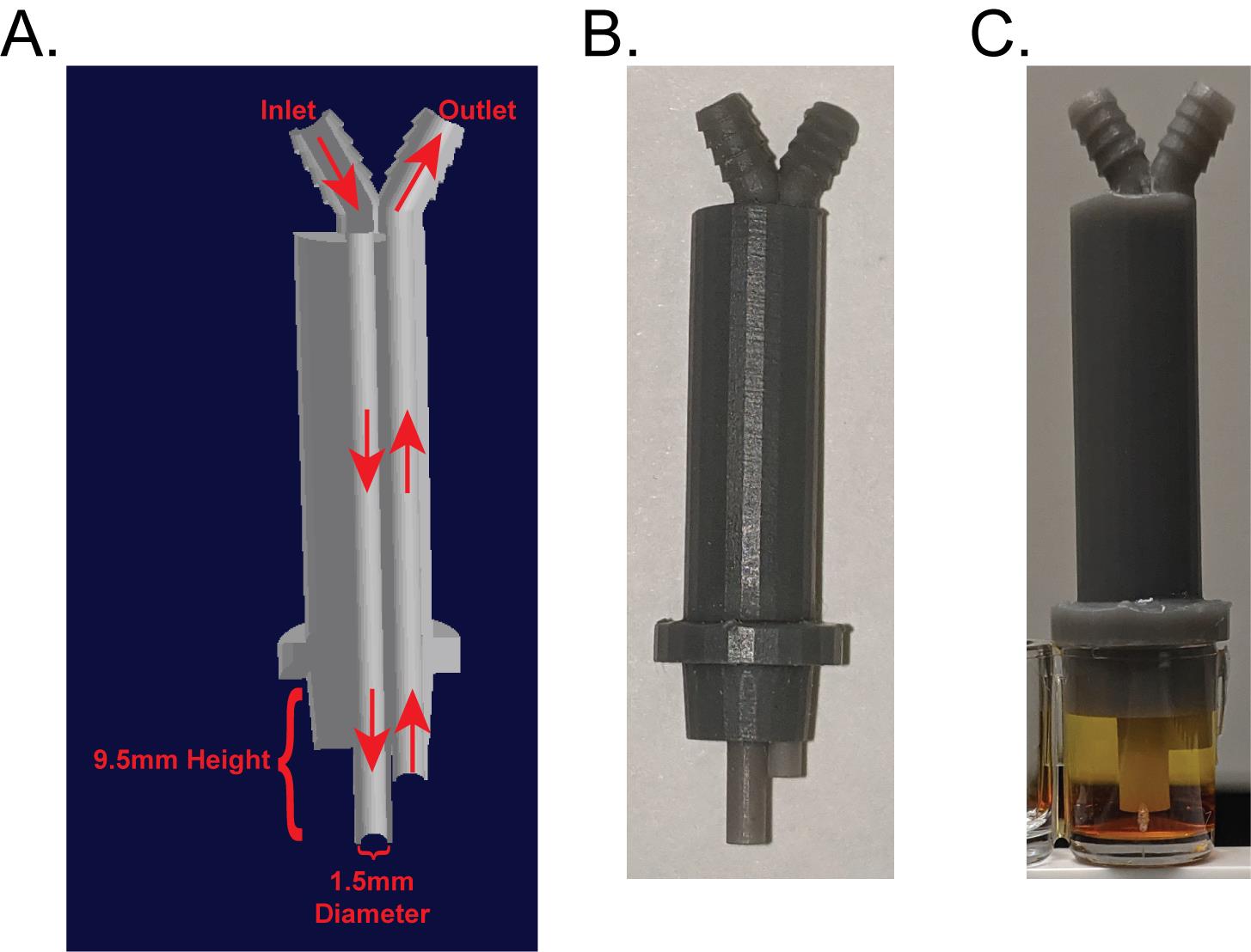
Figure 1. Dimensions of FSS tip used to induce sclerostin degradation. (A) Cross-section cut away of the 3D printed FSS tip. (B) Representative 3D printed FSS tip. (C) FSS tip in a well of a 96-well plate filled with colored water. Note that the tip “skirt” is flush with the top of the well and there are no air bubbles in the well. Note that sclerostin degradation stimulated with this device has also been replicated with Ibidi Chambers (Lyons et al., 2016).
Procedure
Prepare sterile filtered Ringer’s solution with calcium (see Recipes).
Sterile Ringer’s is stored at 4°C until use, when it is aliquoted and warmed to 37°C.
Plating Ocy454 cells
Ocy454 cells are maintained at 33°C, 5% CO2 on collagen-coated 150 mm dishes in complete αMEM at less than 50% confluency to maintain sclerostin expression (Figure 2).
Multiple plates of the same passage of cells can be pooled together to ensure there are enough cells to plate for an experiment because they are cultured at such low density.
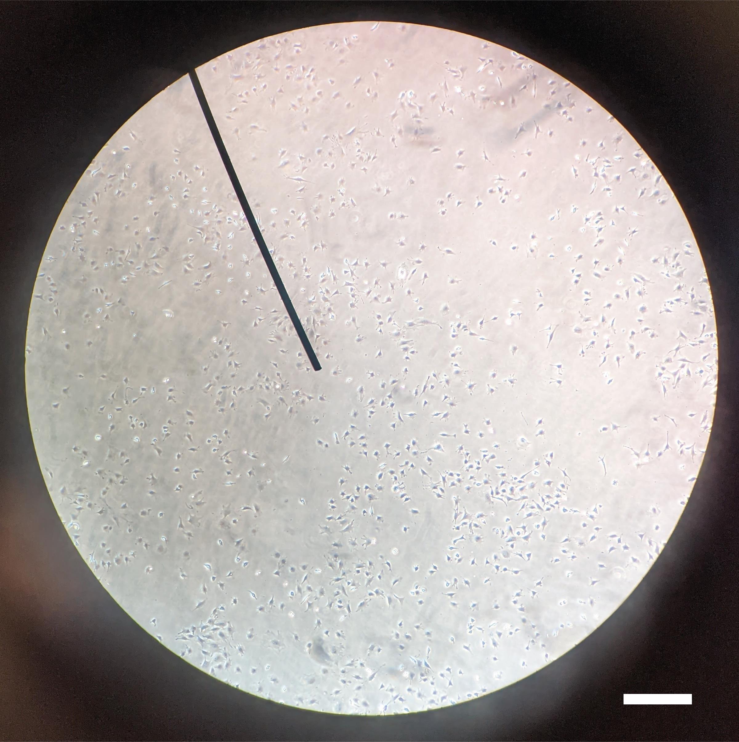
Figure 2. Ocy454 culture confluency prior to plating for FSS experiment. Ocy454 cells should be maintained at 33°C, 5% CO2 in complete αMEM on collagen coated dishes at less than 50% confluency to maintain sclerostin expression. After plating for FSS, Ocy454 cells are cultured at 37°C, 5% CO2. Scale bar = 0.4 mm.Aspirate media of plated cells.
Rinse Ocy454 cells with 10 ml of HBSS and aspirate.
Add 2 ml of trypsin/EDTA solution to the 150 mm dish and swirl to cover the plate.
Aspirate off extra trypsin/ETDA and allow cells to detach at 37°C, 5% CO2 for 5 min or less until all cells are free-floating.
Add 2 ml of complete αMEM per 150 mm dish to neutralize trypsin/EDTA, collect cells, and transfer cell suspension to a conical tube.
If multiple dishes are being pooled, combine all cells into a single conical tube for cell counting to have a homogenous cell suspension and to prevent variance due to different plates of cells used for the same experiment.
Because cells are plated at such low density, using the smallest amount of media/trypsin allows for cells to be more concentrated to allow for plating in small volumes.
Count cells using a cell counter or hemocytometer.
Plate Ocy454 cells at a density of 125,000 cells/cm2 (40,000 cells/well in a 96-well plate) in a total volume of 200 μl/well into the necessary number of wells in 1×8 well strips 96-well plate (example plate set up is shown in Figure 5A).
Culture cells overnight at 37°C, 5% CO2.
Longer culture times (many labs use 14 days) at 37°C, 5% CO2 increases sclerostin protein abundance (Spatz et al., 2015).
Preparing for FSS and calibrating the peristaltic pump
Turn on warming mat and oven and set both to 37°C.
Aliquot the appropriate amount of Ringer’s solution into 50 ml conical tubes and warm them to 37°C.
Turn on FSS pump, which will take you to the home screen (Figure 3).
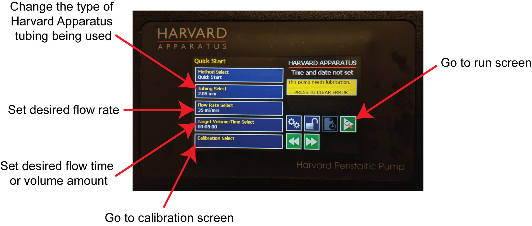
Figure 3. Run screen on Harvard Apparatus Pump. From this screen, you can enter the type of tubing being used, set the flow rate, time, and volume, go to the run screen, and go to the calibration screen.Ensure the tubing type is correct (recommend using Purple/Purple 2.06 mm tubing from Harvard Apparatus) and is loaded into pump cassettes.
Calibrate peristaltic pump to ensure flow rate is correct (calibration is done before the FSS tips are attached).
Fill a 50 ml conical tube with MilliQ water.
Place one tubing inlet into the 50 ml conical and fill the entire tubing with water (ensure water comes out the outlet and that there are no large air bubbles in the tubing).
Place outlet of filled tubing into an empty graduated cylinder.
Go to the calibration screen by pressing the Calibration Select button (Figure 3).
Under calibration tab (Figure 4A-4C), start the pump (Figure 4A), allow it to run for one minute, then stop the pump.
Ensure the inlet stays in the conical tube of water and that the water does not run out, or the inlet stops taking in water. Make sure the outlet stays in the graduated cylinder.
Determine the volume dispensed into the graduated cylinder, press the Enter Volume Delivered button (Figure 4B) to input the volume dispensed using the keypad buttons (Figure 4C), and press the green check button.
The pump will now automatically return to the home screen as the calibration cycle is complete.
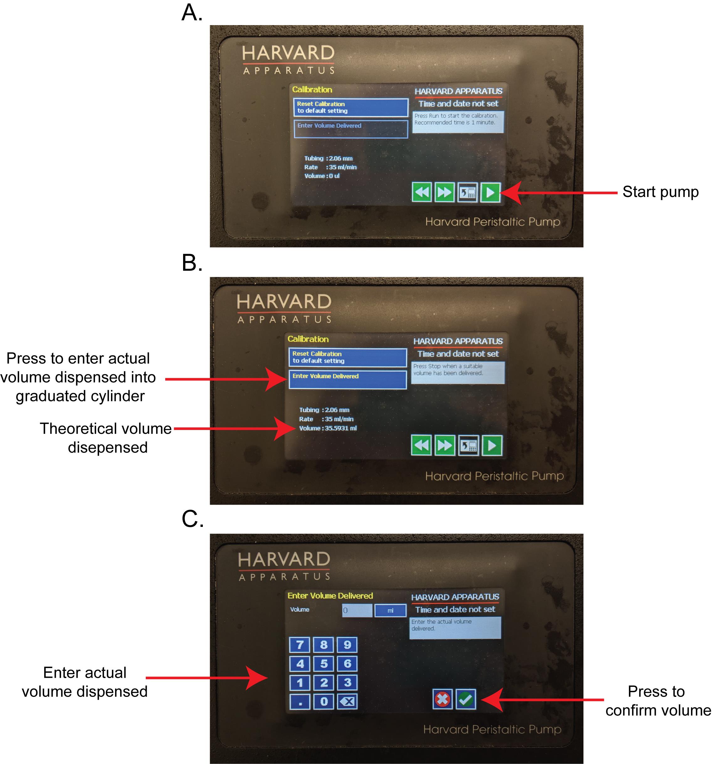
Figure 4. Work flow for pump calibration. (A) The calibration screen. Press the green triangle “play” button to begin the pump. The theoretical volume dispensed will increase as the pump runs. (B) After flowing for about 1 min, press the red square “stop” button to stop the pump. Press the “Enter Volume Dispensed” button. (C) Using the number pad, enter the actual volume dispensed into the graduated cylinder and press the green check button.Settings on the pump are now reset. Set the flow rate on the pump to 35 ml/min and flow time to 1 min (Figure 3).
Empty graduated cylinder back into the 50 ml conical tube of water and place the outlet tubing back into the now empty graduated cylinder and the inlet into the conical tube of water.
In the run screen, run a full pump cycle for 1 min at 35 ml/min into the graduated cylinder to ensure calibration is correct.
If pump is ± 2 ml from set rate, recalibrate using procedure described in Steps C5-C8.
If calibration cannot be achieved within this 2 ml error, the tubing may need to be replaced and rotor lubricated.
Set desired flow rate (typically 35 ml/min) and flow time (typically 1-5 min).
These parameters permit assessment of rapid mechano-transduction events, such as CaMKII activation and sclerostin degradation, as described here (Lyons et al., 2017; Williams et al., 2020; Gould et al., 2021).
Run calibration protocol before every fluid shear stress experiment or any time the pump has been turned off.
Fluid Shear Stress
Prepare a sufficient volume of lysis buffer to lyse the appropriate number of wells of a 96-well plate using 20-30 μl of RIPA per well.
Take a strip of Ocy454 cells plated into the 1×8 well 96-well plate out of the cell culture incubator and place into a new 96-well rack (Figure 5A).
This allows any cells not currently being treated or exposed to FSS to remain stagnant and in complete αMEM.
Move this strip of cells to the warming mat near the FSS pump and the benchtop oven.
Once cells are moved into Ringer’s, experiments can be run at atmospheric CO2.
Bench set-up should contain vacuum pump for aspiration, Harvard Apparatus pump, warming mat, and oven in close proximity, to allow for as much reduction of movement as possible once cells are in Ringer’s.
Aspirate MEM media and fill each well to the top with warmed Ringer (each well will require about 350 μl).
Place rack into the 37°C oven or keep plate on warming mat on benchtop for 15-20 min, to allow cells to equilibrate in the Ringer’s solution and to ensure any mechano-events activated by exchanging the media for Ringer’s can reset (Donahue et al., 2003).
During this 15-20 min wait time, attach FSS tips to the pump tubing, ensuring the inlet and outlets on each tip are on the correct flow direction.
There are arrows on the pump cassettes to indicate the inflow and outflow direction (Figure 5B).
Pour warm Ringer’s into a fluid reservoir.
Place the FSS tips attached to the tubing into the fluid reservoir.
Place them on their sides with the inlet facing up and stagger where they lay to help prevent circulation of bubbles (Figure 5C).
Fill the sets of tubing with warmed Ringer’s solution, ensuring all bubbles are removed from the tubing.
Each tube takes about 3 ml of Ringer’s to fill completely.
Start and stop the pump as needed; you do not need to run a full timed cycle to fill the tubing and FSS tips.
Insert the 3D tips into every other well as FSS tips do not fit flush to the plate if they overlap (Figures 1C, 5D). Indeed, this orientation allows for the adjacent well, lacking a FSS tip, to be used as the time/treatment matched no flow control (Figure 5D).
Push the FSS tip straight down into the well. Do not wiggle the FSS tip once it is in the well, as this may introduce bubbles. Ensure the lip of the FSS tip is flush with the top of the well and is secure with no bubbles in the well (Figure 1C).
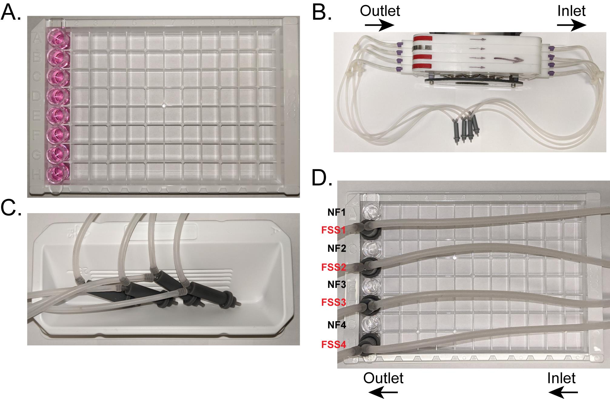
Figure 5. Set-up of 96-well plate and pump for FSS. (A) A single 1×8 strip that is seeded with Ocy454 cells is moved into a new rack for transfer to the benchtop for FSS. Media is replaced with Ringer’s prior to FSS. (B) FSS tips are connected to the tubing, ensuring the long inlet on the tip is connected to the inlet direction of the pump. (C) To fill up the tubing and FSS tips with Ringer’s before placing into wells for FSS, place them on their side in a Ringer’s filled solution reservoir. This allows for fewer bubbles to be taken up into the tubing and makes it easier to fill the tubing efficiently. (D) FSS tips are placed into every other well so they can sit flush with the top of each well. The wells without a FSS tip can then act as time/treatment matched no flow controls. NF – no flow control, FSS – well exposed to FSS.Start the pump and apply FSS.
After FSS ends and the appropriate post flow incubation has occurred [e.g., we find that after FSS, immediate lysis or lysis after 10 min allows us to assess CaMKII activation and/or sclerostin protein loss (Lyons et al., 2016 and 2017; Williams et al., 2020; Gould et al., 2021)], aspirate the Ringer’s from each well, both no flow and FSS wells.
If waiting to lyse cells, remove FSS tips, but do NOT aspirate Ringer’s, and keep the plate flat and unmoved on the warming mat for desired time before aspirating off Ringer’s for lysis
To lyse cells, quickly add 20-30 μl of the prepared lysis buffer to each well and place entire plate onto ice
Using a new pipette tip for each well, or each set of pooled wells, scrape the monolayer of cells to ensure sufficient lysis, and transfer lysate into labeled Eppendorf tubes.
To increase cell lysate amount to allow for increased sclerostin abundance or increased sample volume for multiple western blots, two or more wells of cell lysates can be pooled together. Ensure the same number of wells are pooled for each no flow and FSS sample.
Discard used FSS Ringer’s solution. Alternatively, this can be collected to analyze secreted factors.
Start and stop the pump as needed to remove all Ringer’s from the tubing.
Repeat FSS (section D) protocol for as many 1×8 strips as necessary.
The 15-20 min wait times can be staggered as needed to be more time efficient.
After all samples are collected, they can be processed for western blotting to evaluate cellular responses.
After the last batch of cells is subjected to FSS, remove all Ringer’s from the tubing. Rinse all tubing and FSS tips with MilliQ water by running a 1-min protocol, then empty tubing of all liquid.
Detecting sclerostin degradation by western blotting
Sonicate samples using a probe sonicator on ice, centrifuge at 15,000 RPM for 2 min in a benchtop centrifuge to pellet the cell debris, and collect the supernatant in a different tube.
Add sufficient volume of 4× Laemmli Sample Buffer +β-mercaptoethanol to a final concentration of 1×.
Add 100 μl β-mercaptoethanol to 900 μl of 4× Laemmli Sample Buffer to result in a final concentration of 355 mM β-mercaptoethanol.
Heat samples to 95°C for 5 min and cool on ice before running on a Tris/Glycine SDS-PAGE gel.
Transfer using a semi-dry method onto PVDF membranes.
After transfer, dry membranes completely for at least 2 h or overnight.
Rewet membranes in methanol, rinse with water to remove excess methanol, and block in 5% non-fat milk + 3% BSA in 1× PBS + 0.1% Tween-20 for 1 h at room temperature (RT) with shaking.
Notes:
A blocking solution with 5% non-fat milk + 3% BSA is required to detect sclerostin, as non-fat milk alone is not sufficient.
For detection of other targets, such as CaMKII, 5% milk in 1× PBS + 0.1% Tween-20 is sufficient.
Use R&D System sclerostin primary antibody at 1:500 in 5% non-fat milk + 3% BSA in 1× PBS + 0.1% Tween-20 and shake overnight at 4°C.
Wash three times for 5 min with 1× PBS + 0.1% Tween-20 at room temperature with shaking.
Incubate with anti-goat HRP secondary at 1:1000 in 5% non-fat milk + 3% BSA in 1× PBS + 0.1% Tween-20 and shake at room temperature for 1 h at RT.
Wash three times for 5 min with 1× PBS + 0.1% Tween-20 with shaking at RT.
Rinse with water and image using WestFemto ECL reagent (Figure 6).
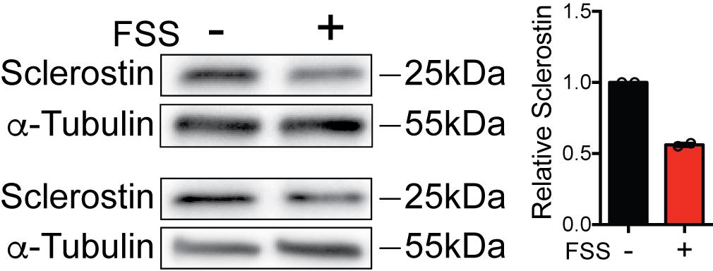
Figure 6. Representative western blots of FSS-Induced Sclerostin Degradation. Ocy454 cells were exposed to 5 min of FSS at 35 ml/min and lysed immediately after the end of FSS. Sclerostin abundance was detected by western blotting with the R&D Systems anti-Sclerostin antibody (n = 2).
Possible experimental adaptations
RT-qPCR
Instead of lysing in 1× RIPA + 2% SDS + HALT protease/phosphatase inhibitor buffer, use 100 μl of cold TRIzol to lyse the cells. Then, proceed with RNA isolation, reverse transcription, and RT-qPCR analysis.
Live cell imaging
When plating Ocy454 cells, use an optically clear, glass-bottom 96-well plate. Cells can be labeled with a nuclear stain, calcium indicators, reactive oxygen species indicators, etc., and can then be subjected to FSS while on an inverted scope that can image in timelapse. This will allow for the monitoring of live cell responses. FSS rate and time can be adjusted to optimize cellular responses for the indicator used.
Analysis of secreted factors
Following FSS, flow buffer from each tubing and supernatant from no flow wells can be collected in conical tubes and used for analysis of secreted factors. Important to note is to consider the differences in volume between the FSS tubing and the no flow wells. Incorporate a dilution factor into the analysis protocol to compensate for the different volume.
Treatment with pharmacological inhibitors
To determine the contribution of certain signaling proteins or cellular responses, cells can be treated with pharmacological inhibitors prior to FSS. If the treatment time is longer than 20 min, pretreat cells in complete MEM at 5% CO2 and 37°C. Then, for the last 20 min of the treatment time, aspirate off drugged media and fully fill wells with drugged Ringer’s solution. Allow cells to equilibrate for 20 min at 37°C, then apply FSS with drugged Ringer’s as described above. Drugged Ringer’s should be used for FSS application to ensure wash-off and reversal of inhibition do not occur.
Notes
The 15-20 min wait time is critical for reproducibility. We have observed that slight movement can induce calcium events that can lead to a refractory period for optimal mechano-activation. This refractory period has been previously reported in cultured osteoblasts (Donahue et al., 2003). While 15-20 min is sufficient for resetting the mechano-transduction cascade necessary for observing sclerostin degradation, this time may need to be altered for other outcome measures. FSS rate, time, and time after FSS before lysis may also need to be optimized for specific outcomes. For sclerostin degradation, 5 min of FSS and up to 10 min of wait time post-flow is sufficient to observe sclerostin degradation, although optimal CaMKII activation precedes this 10 min post flow time point (Gould et al., 2021). 5% milk and 3% BSA are required for the detection of sclerostin by western blotting. Sclerostin appears at the predicted molecular weight of 27 kDa after electrophoresis, as confirmed by comparing banding patterns between cortical bone lysates from wild-type and global sclerostin knockout mice (Williams et al., 2020).
Recipes
1× Ringer’s Solution with Calcium
In a clean glass bottle, add 400 ml of MilliQ water.
Measure out appropriate amounts of reagents below, add to glass bottle, and mix well.
140 mM NaCl
4 mM KCl
1 mM MgSO4
10 mM HEPES
10 mM Sucrose
5 mM NaHCO3
1.8 mM CaCl2
Adjust the pH of the solution to 7.2-7.4 using HCl and NaOH. Use as small amounts as possible to not drastically alter the ion concentrations.
Adjust total volume to 500 ml.
Using a 0.22 µm sterile filter setup, sterile filter the Ringer’s solution.
Store at 4°C until the day of use, then warm the volume needed to 37°C in conical tubes.
Ensure nothing is growing in the stock bottle (i.e., cloudy appearance, sediment in bottom of bottle).
Transfer Buffer
48 mM Tris Base
39 mM Glycine
0.04% SDS
20% Methanol
Adjust total volume to 1 L with MilliQ water
1× RIPA/SDS/HALT Lysis Buffer
First, make the 10% SDS stock solution by mixing 10 g of SDS into 80 ml of MilliQ water.
Once dissolved, adjust the total volume to 100 ml with additional MilliQ water.
To make 1 ml of 1× Lysis Buffer, dilute together:
100 μl of 10× RIPA Buffer
200 μl of 10% SDS solution
700 μl of MilliQ water
10 μl of HALT Protease Inhibitor Cocktail
Vortex the solution for sufficient mixing; this will result in a lysis buffer with 1× RIPA, 2% SDS, and 1× HALT Protease Inhibitor Cocktail.
Acknowledgments
This work was supported by funding from NIH (AR071614, JPS and CWW; AR063631, JPS; AR071618, HL142290, CWW; GM008181 and AR077974, NRG). This protocol (the 3D printed FSS tips, CaMKII activation, and sclerostin degradation) is derived from previous publications (Lyons et al., 2016, 2017; Williams et al., 2020; Gould et al., 2021 [DOI: 10.7554/eLife.64393]).
Competing interests
Joseph P Stains holds two patents related to this work. One for the custom fluid shear device used for these experiments (US Patent No US 2017/0276666 A1) and a second for the targeting microtubules (part of this mechano-transduction pathway) to improve bone mass (US Patent No US 2019/0351055 A1). Ramzi J Khairallah has a patent pending on colchicine analogs to treat musculoskeletal disorders (PCT/US2018/038300). Ramzi J. Khairallah is affiliated with Myologica, LLC. The author has no financial interests to declare. Christopher W Ward holds two patents related to this work. One for the custom fluid shear device used for these experiments (US Patent No US 2017/0276666 A1) and a second for the targeting microtubules (part of this mechano-transduction pathway) to improve bone mass (US Patent No US 2019/0351055 A1). Another patent on colchicine analogs to treat musculoskeletal disorders is pending (PCT/US2018/038300). The other authors declare that no competing interests exist.
References
- Aryaei, A. and Jayasuriya, A. C. (2015). The effect of oscillatory mechanical stimulation on osteoblast attachment and proliferation. Mater Sci Eng C Mater Biol Appl 52: 129-134.
- Bacabac, R. G., Smit, T. H., Mullender, M. G., Dijcks, S. J., Van Loon, J. J. and Klein-Nulend, J. (2004). Nitric oxide production by bone cells is fluid shear stress rate dependent. Biochem Biophys Res Commun 315(4): 823-829.
- Delaine-Smith, R. M., MacNeil, S. and Reilly, G. C. (2012). Matrix production and collagen structure are enhanced in two types of osteogenic progenitor cells by a simple fluid shear stress stimulus. Eur Cell Mater 24: 162-174.
- Delgado-Calle, J., Sato, A. Y. and Bellido, T. (2017). Role and mechanism of action of sclerostin in bone. Bone 96: 29-37.
- Donahue, S. W., Donahue, H. J. and Jacobs, C. R. (2003). Osteoblastic cells have refractory periods for fluid-flow-induced intracellular calcium oscillations for short bouts of flow and display multiple low-magnitude oscillations during long-term flow. J Biomech 36(1): 35-43.
- Frangos, J. A., Eskin, S. G., McIntire, L. V. and Ives, C. L. (1985). Flow effects on prostacyclin production by cultured human endothelial cells. Science 227(4693): 1477-1479.
- Genetos, D. C., Geist, D. J., Liu, D., Donahue, H. J. and Duncan, R. L. (2005). Fluid shear-induced ATP secretion mediates prostaglandin release in MC3T3-E1 osteoblasts. J Bone Miner Res 20(1): 41-49.
- Gould, N. R., Williams, K. M., Joca, H. C., Torre, O. M., Lyons, J. S., Leser, J. M., Srikanth, M. P., Hughes, M., Khairallah, R. J., Feldman, R. A., et al. (2021). Disparate bone anabolic cues activate bone formation by regulating the rapid lysosomal degradation of sclerostin protein. Elife 10: e64393.
- Hillsley, M. V. and Frangos, J. A. (1997). Alkaline phosphatase in osteoblasts is down-regulated by pulsatile fluid flow. Calcif Tissue Int 60(1): 48-53.
- Jacobs, C. R., Yellowley, C. E., Davis, B. R., Zhou, Z., Cimbala, J. M. and Donahue, H. J. (1998). Differential effect of steady versus oscillating flow on bone cells. J Biomech 31(11): 969-976.
- Klein-Nulend, J., Burger, E. H., Semeins, C. M., Raisz, L. G. and Pilbeam, C. C. (1997). Pulsating fluid flow stimulates prostaglandin release and inducible prostaglandin G/H synthase mRNA expression in primary mouse bone cells. J Bone Miner Res 12(1): 45-51.
- Lim, K. T., Hexiu, J., Kim, J., Seonwoo, H., Choung, P. H. and Chung, J. H. (2014). Synergistic effects of orbital shear stress on in vitro growth and osteogenic differentiation of human alveolar bone-derived mesenchymal stem cells. Biomed Res Int 2014: 316803.
- Lu, X. L., Huo, B., Park, M. and Guo, X. E. (2012). Calcium response in osteocytic networks under steady and oscillatory fluid flow. Bone 51(3): 466-473.
- Lyons, J. S., Iyer, S. R., Lovering, R. M., Ward, C. W. and Stains, J. P. (2016). Novel multi-functional fluid flow device for studying cellular mechanotransduction. J Biomech 49(16): 4173-4179.
- Lyons, J. S., Joca, H. C., Law, R. A., Williams, K. M., Kerr, J. P., Shi, G., Khairallah, R. J., Martin, S. S., Konstantopoulos, K., Ward, C. W. and Stains, J. P. (2017). Microtubules tune mechanotransduction through NOX2 and TRPV4 to decrease sclerostin abundance in osteocytes. Sci Signal 10(506): eaan5748.
- Reich, K. M. and Frangos, J. A. (1991). Effect of flow on prostaglandin E2 and inositol trisphosphate levels in osteoblasts. Am J Physiol 261(3 Pt 1): C428-432.
- Robling, A. G., Niziolek, P. J., Baldridge, L. A., Condon, K. W., Allen, M. R., Alam, I., Mantila, S. M., Gluhak-Heinrich, J., Bellido, T. M., Harris, S. E. et al. (2008). Mechanical stimulation of bone in vivo reduces osteocyte expression of Sost/sclerostin. J Biol Chem 283(9): 5866-5875.
- Spatz, J. M., Wein, M. N., Gooi, J. H., Qu, Y., Garr, J. L., Liu, S., Barry, K. J., Uda, Y., Lai, F., Dedic, C., et al. (2015). The Wnt Inhibitor Sclerostin Is Up-regulated by Mechanical Unloading in Osteocytes in Vitro. J Biol Chem 290(27): 16744-16758.
- Tu, X., Rhee, Y., Condon, K. W., Bivi, N., Allen, M. R., Dwyer, D., Stolina, M., Turner, C. H., Robling, A. G., Plotkin, L. I. et al. (2012). Sost downregulation and local Wnt signaling are required for the osteogenic response to mechanical loading. Bone 50(1): 209-217.
- Tucker, R. P., Henningsson, P., Franklin, S. L., Chen, D., Ventikos, Y., Bomphrey, R. J. and Thompson, M. S. (2014). See-saw rocking: an in vitro model for mechanotransduction research. J R Soc Interface 11(97): 20140330.
- Williams, K. M., Leser, J. M., Gould, N. R., Joca, H. C., Lyons, J. S., Khairallah, R. J., Ward, C. W. and Stains, J. P. (2020). TRPV4 calcium influx controls sclerostin protein loss independent of purinergic calcium oscillations. Bone 136: 115356.
- Winkler, D. G., Sutherland, M. K., Geoghegan, J. C., Yu, C., Hayes, T., Skonier, J. E., Shpektor, D., Jonas, M., Kovacevich, B. R., Staehling-Hampton, K., et al. (2003). Osteocyte control of bone formation via sclerostin, a novel BMP antagonist. EMBO J 22(23): 6267-6276.
- Wittkowske, C., Reilly, G. C., Lacroix, D. and Perrault, C. M. (2016). In Vitro Bone Cell Models: Impact of Fluid Shear Stress on Bone Formation. Front Bioeng Biotechnol 4: 87.
- Young, S. R., Hum, J. M., Rodenberg, E., Turner, C. H. and Pavalko, F. M. (2011). Non-overlapping functions for Pyk2 and FAK in osteoblasts during fluid shear stress-induced mechanotransduction. PLoS One 6(1): e16026.
Article Information
Copyright
![]() Gould et al. This article is distributed under the terms of the Creative Commons Attribution License (CC BY 4.0).
Gould et al. This article is distributed under the terms of the Creative Commons Attribution License (CC BY 4.0).
How to cite
Readers should cite both the Bio-protocol article and the original research article where this protocol was used:
- Gould, N. R., Leser, J. M., Torre, O. M., Khairallah, R. J., Ward, C. W. and Stains, J. P. (2021). In vitro Fluid Shear Stress Induced Sclerostin Degradation and CaMKII Activation in Osteocytes. Bio-protocol 11(23): e4251. DOI: 10.21769/BioProtoc.4251.
- Gould, N. R., Williams, K. M., Joca, H. C., Torre, O. M., Lyons, J. S., Leser, J. M., Srikanth, M. P., Hughes, M., Khairallah, R. J., Feldman, R. A., et al. (2021). Disparate bone anabolic cues activate bone formation by regulating the rapid lysosomal degradation of sclerostin protein. Elife 10: e64393.
Category
Cell Biology > Cell signaling > Intracellular Signaling
Biological Engineering > Biomedical engineering
Do you have any questions about this protocol?
Post your question to gather feedback from the community. We will also invite the authors of this article to respond.