

A Novel Imaging Protocol for Investigating Arabidopsis thaliana Siliques and Seeds Using X-rays
使用 X 射线研究拟南芥长角果和种子的新型成像方案

发布: 2023年10月05日第13卷第19期 DOI: 10.21769/BioProtoc.4839 浏览次数: 2219
评审: Samik BhattacharyaSwati MeghaDawid S Zyla
Advertisement


Abstract
Understanding silique and seed morphology is essential to developmental biology. Arabidopsis thaliana is one of the best-studied plant models for understanding the genetic determinants of seed count and size. However, the small size of its seeds, and their encasement in a pod known as silique, makes investigating their numbers and morphology both time consuming and tedious. Researchers often report bulk seed weights as an indicator of average seed size, but this overlooks individual seed details. Removal of the seeds and subsequent image analysis is possible, but automated counts are often impossible due to seed pigmentation and shadowing. Traditional ways of analyzing seed count and size, without their removal from the silique, involve lengthy histological processing (24–48 h) and the use of toxic organic solvents. We developed a method that is non-invasive, requires minimal sample processing, and obtains data in a short period of time (1–2 h). This method uses a custom X-ray imaging system to visualize Arabidopsis siliques at different stages of their growth. We show that this process can be successfully used to analyze the overall topology of Arabidopsis siliques and seed size and count. This new method can be easily adapted for other plant models.
Key features
• No requirement for organic solvents for imaging siliques.
• Easy image capture and rapid turnaround time for obtaining data.
• Protocol may be easily adapted for other plant models.
Graphical overview
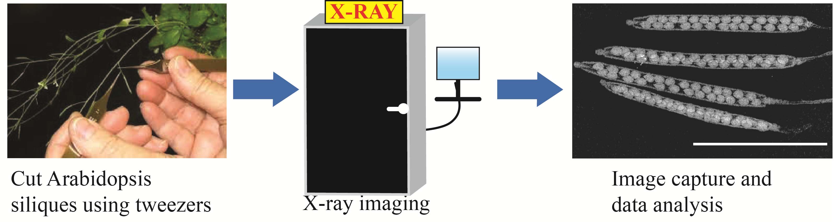
Arabidopsis siliques using the Inspex 20i X-ray machine
Background
Seed development is critical for the survival of all flowering plants (Jardinaud and Petitprez, 2003). Of the current plant models, Arabidopsis thaliana, with its convenient seed pod (silique), continues to be the most widely used tool for studying fruit/seed development and morphogenesis (Bates et al., 2013; Kao and Nodine, 2021). Arabidopsis siliques contain rigid cell walls and are pigmented by chlorophyll, which makes analyses of seed morphology, anatomy, and ultrastructure challenging (Hedhly et al., 2018; Attuluri et al., 2022;). To overcome these difficulties, conventional methods employ different types of fixatives (e.g., Acryloyl-X, FPA50) and optical clearing reagents (e.g., chloral hydrate, 2,2’-thiodiethanol, sodium dodecyl sulfate) for whole-mount microscopy (Hedhly et al., 2018; Attuluri et al., 2022). Despite their pervasive use, these methods are tedious, as these clearing procedures have specific protocols that involve the use of harmful organic solvents and lengthy (> 24 h) durations (Attuluri et al., 2022). Hence, there is a growing demand for non-invasive techniques that can provide high-quality digital data with shorter turnaround times and avoid the use of toxic organic solvents. In the work presented here, we describe a new, non-invasive technique for visualizing Arabidopsis siliques with seeds at different stages of their growth using a custom X-ray imaging system. While X-ray microscopy has been used for imaging flower development in Arabidopsis (Prunet and Duncan, 2020), studies of seed and silique development continue to rely mostly on conventional histological methods. We show that with minimal sample processing, without any use of toxic organic solvents, high-quality images can be captured with our custom X-ray imaging system (in 1–2 h) for downstream processing and data analyses. Statistical tests using one-way ANOVA and frequency distribution show high reproducibility and consistency of seed count and seed diameter in dried Arabidopsis siliques across three independent experiments. Taken together, our easy-to-use X-ray system serves as a new imaging tool for visualizing Arabidopsis siliques and seeds and, with some modification, can be adapted for other plant models.
Materials and reagents
Biological materials
Arabidopsis thaliana ecotype Columbia (Col_0) plant at midflowering, complete flowering, and seed harvest stage (Boyes et al., 2001).
Laboratory supplies
Fine precision medium tipped tweezers/forceps (Fisher Scientific, catalog number: 12-000-157)
Petri dish (Fisher Scientific, catalog number: FB0875712)
Permanent ink markers
Paper towels (Fisher Scientific, catalog number: 19-040-898)
Tape (Fisher Scientific, catalog number: 15949)
X-ray source: Kevex PXS10-16W MicroFocus system
Boss LS-1416 CO2 laser cutter
Equipment
Inspex 20i X-ray machine
For custom manufacturing of the X-ray imaging cabinet, details are provided in Figure 1. The Inspex 20i X-ray machine was assembled by Kodex Inc. (Nutley, NJ).
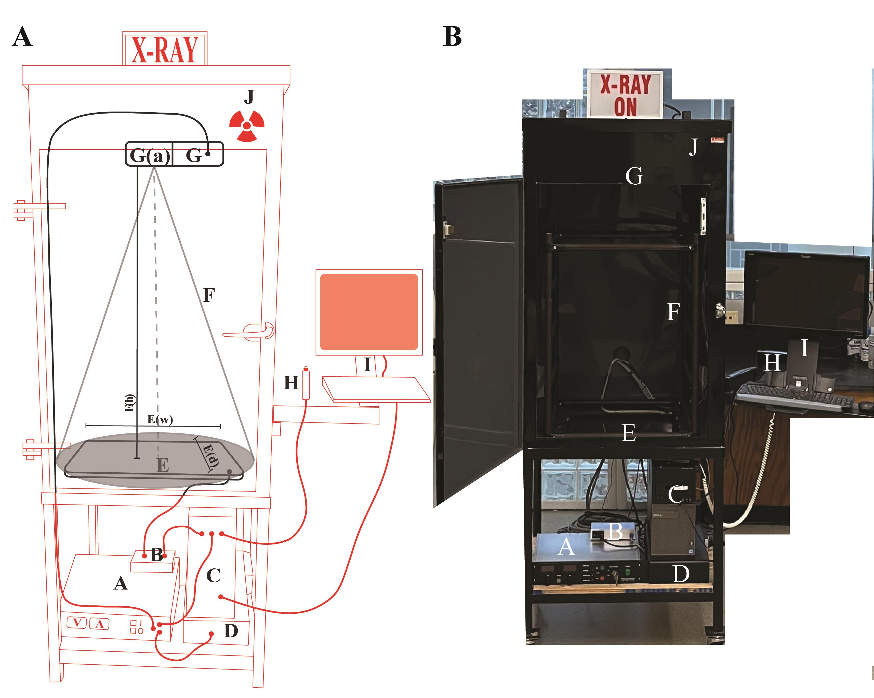
Figure 1. Schematics of the X-ray imaging setup. (A) Cartoon sketch of the Inspex 20i X-ray machine with all the accessories. The custom steel cabinet (J) measures 64.77 cm (depth) × 127 cm (height) × 78.74 cm (width) and is lined with a lead sheet to conform to BRH 21 CFR 1020.40 and FDA 21 CFR 1020.40, in accordance with Georgia State X-ray radiation regulations. The X-ray source (G) is a Kevex PXS10-16W MicroFocus system that produces a downward facing cone-beam so that shadows can be detected on the Kodex LTX-1717 digital detection panel (E) located at the bottom of the cabinet. This amorphous silicon flat panel detector has a cesium iodide scintillator in the outer layer that allows for the conversion of X-rays to light, which is then digitized by the photodiode layer below for transmission to the computer for display on the screen. The microfocus system allows focused images to be enlarged or reduced by varying the specimen height between the source and detector (closer to the source results in a magnified image). Placing the specimen as close as possible to the source (G(a)) results in a field of view of approximately 9.5 mm2. The field of view adjacent to the detector (E) is approximately 45 times greater at 431.8 mm2 (the detector is 17 × 17 inches). Components external to the cabinet (red): (A) Power supply for the X-ray source; (B) Power supply and data transfer unit for the detector; (C) Computer to render and save images; (D) Uninterruptable power supply and surge suppressor for the X-ray machine. Components inside the cabinet (black): (E) The Kodex LTX-1717 digital detection panel, E(w) width 44.45 cm, E(d) depth 44.45 cm, E(h) distance between detector and source 104.14 cm; (F) The cone beam path of the X-ray (cone of illumination, 53°); (G) The Kevex PXS10 MicroFocus X-ray source (maximum settings of 80 kV, 0.100 mA); (H) Image collection shutter trigger; (I) Touchscreen monitor and keyboard for image viewing. (Average settings for this study: Silique specimens in this study were placed on a low-density plastic platform suspended 98.4 cm above the detector, and the source was operated at 40 kV and 0.09 Amps). (B) Picture of the X-ray machine with the front door open.Scale for the measurement of siliques/seeds using the Inspex 20i X-ray machine
We used an X-ray semi-transparent scale that was cut from cardstock (weight 90 Lb) using a Boss LS-1416 CO2 laser cutter (70 W). We did this because the printed hashmarks on solid plastic or metal rulers are not visible in X-ray images. We designed the scale using the Adobe Illustrator vector drawing package. Only the millimeter hashmarks and the external contour of the scale were cut; the millimeter number markings were not. The kerf width of the laser cutter (aka. hashmark line width) measured an average of 0.152 mm. This was wider than we had hoped, but the centers of the marks were extremely accurate. The dimensional accuracy of the laser cutter was listed as being ± 0.0127 mm, and this high accuracy was confirmed using multiple micrometer measurements from the hashmark centers. Since the scale bars and their hashmarks could be seen beside the seeds and siliques, they proved a simple, economical, and reproducible method of calibrating X-ray image dimensions.
Software and datasets
VetView Console: All-In-One Workstation Software is used for image acquisition, processing, and editing.
DaVinci Resolve 11: Calibration software, run as a script, to dark calibrate data read from the X-ray detector while the source is not providing illumination.
FIJI ImageJ Build 2.13.1: This image processing program was used to count and measure diameters of the seeds within the silique.
GraphPad Prism Version 9.4.1: Statistical analyses and production of graphs.
Procedure
文章信息
版权信息
© 2023 The Author(s); This is an open access article under the CC BY license (https://creativecommons.org/licenses/by/4.0/).
如何引用
Ritchie, B. A., Uyeno, T. A., Diaz, D. F. R. and Lokdarshi, A. (2023). A Novel Imaging Protocol for Investigating Arabidopsis thaliana Siliques and Seeds Using X-rays. Bio-protocol 13(19): e4839. DOI: 10.21769/BioProtoc.4839.
分类
植物科学 > 植物发育生物学 > 形态建成
植物科学 > 植物育种 > 种子品质
您对这篇实验方法有问题吗?
在此处发布您的问题,我们将邀请本文作者来回答。同时,我们会将您的问题发布到Bio-protocol Exchange,以便寻求社区成员的帮助。