

Mechanical Characterization of Glandular Acini Using a Micro-indentation Instrument
使用微压痕仪对腺泡进行机械表征
发布: 2020年12月05日第10卷第23期 DOI: 10.21769/BioProtoc.3847 浏览次数: 4407
评审: Sourav S PatnaikFereshteh AzediAnonymous reviewer(s)
参见作者原研究论文
The authors used this protocol in:

Sep 2019
Advertisement


Abstract
The linker of nucleoskeleton and cytoskeleton (LINC) complex is responsible for tethering the nucleus to the cytoskeleton, providing a pathway for the cell’s nucleus to sense mechanical signals from the environment. Recently, we explored the role of the LINC complex in the development of glandular epithelial acini, such as those found in kidneys, breasts, and other organs. Acini developed with disrupted LINC complexes exhibited a loss of structural integrity, including filling of the lumen structures. As part of our investigation, we performed a mechanical indentation assay of LINC disrupted and undisrupted MDCK II cells using a micro-indentation instrument mounted above a laser-scanning confocal microscope. Through a combination of force measurements acquired from the micro-indentation instrument and contact area measurements taken from fluorescence images, we determined the average contact pressure at which the acini structure ruptured. Here, we provide a detailed description of the design of the micro-indentation instrument, as well as the experimental steps developed to perform these bio-indentation measurements. Furthermore, we discuss the data analysis steps necessary to determine the rupture pressure of the acini structures. While this protocol is focused on the indentation of individual glandular acini, the methods presented here can be adapted to perform a variety of mechanical indentation experiments for both 2D and 3D biological systems.
Keywords: Bio-indentation (生物压痕)Background
Bio-indentation measurements have emerged as means to measure the material properties of biological systems at length scales ranging from sub-cellular biopolymers to multi-cellular tissue structures. Nano-indentation instruments with micron sized probes and contact areas on the order of 10-100 nm2 have been used to measure the material properties of biopolymers and individual cells (Stolz et al., 2004; Sen et al., 2005; Strasser et al., 2007; Li et al., 2008). Similarly, micro-indentation instrument with millimeter sized indentation tips and contact areas on the order of 10-100 µm2 have been used to study the collective behavior and responses of cellular structures to external mechanical forces (Ahn et al., 2010; Levental et al., 2010; Schulze et al., 2017). Exploring cellular responses to mechanical queues from the micro-environment is crucial toward understanding how cells regulate growth, undergo differentiation or morphological changes, and express various genes (Vogel and Sheetz, 2006).
Transmission of mechanical signals from the cytoplasmic cytoskeleton to the nuclear envelope occurs through an assembly of proteins collectively referred to as the linker of nucleoskeleton and cytoskeleton (LINC) complex (Crisp et al., 2006). In addition to facilitating the mechanotransduction of signals to the nucleus, the LINC complex is responsible for tethering the nucleus to the cytoskeleton and regulating cytoplasmic filament organization (Crisp et al., 2006; Lei et al., 2009; Mellad et al., 2011; Tapley and Starr, 2013). Disruption of the LINC complex has been proposed as a potential pathway in the development of a variety of human diseases including cancerous development in glandular epithelia; a reduction in the expression of LINC complex proteins, including SUN1, SUN2, nesprin-2, and lamin A/C, has been observed in breast cancer tissues (Debnath and Brugge, 2005; Horn et al., 2013; Meinke et al., 2014; Matsumoto et al., 2015). However, the precise role that the loss of the LINC complex plays during malignant transformation is not well understood. Recently, we explored the effect of LINC complex disruption on the development and maintenance of higher-order cellular structures (Zhang et al., 2019). Development of glandular acini were hindered when the LINC complex was disrupted resulting in the loss of structural integrity and the filling of the lumens in MDCK II and MCF-10A acini. As part of our investigation into the role of the LINC complex in acinar development, we performed a bio-indentation assay of MDCK II acini to determine the average contact pressure required to induce rupture of individual acini structures. MDCK II acini with filled lumens resulting from the disruption of the LINC complex were found to require higher contact pressures to induce rupture compared to undisrupted MDCK II acini.
Here, we present the protocol for performing the mechanical indentation assay of individual MDCK II acini that was developed as part of our exploration into the role the LINC complex plays in acinar development. Through a combination of force measurements recorded using a micro-indentation instrument and fluorescence images captured through confocal microscopy, we measure the pressure necessary to mechanically rupture individual glandular acini. We discuss the design and operation of a micro-indentation instrument capable of applying vertical displacements on the order nanometers and measuring normal forces on the order of micro-Newtons. Additionally, we discuss the experimental protocol necessary to perform these indentation measurements and the data analysis necessary to determine the average contact pressure to rupture the acini structure. While this manuscript is focused on the indentation of individual acini, these methods can be adapted to perform a variety of mechanical indentation explorations of both 2D and 3D biological systems.
Materials and Reagents
The following materials and reagents are used as part of this bio-indentation protocol:
8-well chamber slide (Nunc Lab-Tek, catalog number:154534 )
35 mm glass bottom Petri dish, 20 mm well size #0 thickness (Cell Vis: D35-20-0-N)
Matrigel matrix basement membrane (Corning, catalog number: 35623 )
MDCK II cell line (gifted from Jennifer Lippincott-Schwartz)
MCF-10A cell line (ATCC, CRL-10317 ; RRID: CVCL_0598)
DMEM medium w/ 4.5 g/L glucose (Mediatech Cellgro, catalog number: 23-10-013-CM )
Donor bovine serum (DBS) (Gibco, catalog number: 16030074 )
Ethylenediaminetetraacetic acid (EDTA) (Corning, catalog number: 46034CI )
Sodium orthovanadate (Na3VO4) (Sigma Aldrich, catalog number: S6508 )
Sodium fluoride (NaF) (Sigma Aldrich, catalog number: 67414 )
Calcein AM (Invitrogen, catalog number: C3100MP )
0.25% trypsin (Corning, catalog number: 25053CI )
Poly-L-lysine (Sigma Aldrich, catalog number: P4832 )
Phosphate buffered saline (PBS) solution 1x (Fisher Scientific, catalog number: BP243820 )
F-127 pluronic (Sigma Aldrich, catalog number: P2443 )
Millipore water
MDCK cell growth medium (see Recipes)
MDCK acini indentation medium (see Recipes)
Matrigel wash solution (see Recipes)
Acini dye medium (see Recipes)
F-127 pluronic solution (see Recipes)
Equipment
The following equipment is used as part of this bio-indentation protocol:
Micro-indentation Instrument:
Sapphire indentation tip (Edmund Optics, catalog number: 48-430 )
Capacitance load cell
Nylon M6 threaded rod (McMaster-Carr, catalog number: 98882A249 )
Nylon M6 hexagonal nut (McMaster-Carr, catalog number: 93800A600 )
Aluminum mount for cantilever beam (custom-built)
Vertical precision Z-positioner (Physik Instrumente, model: P-622.ZCL PIHera )
Aluminum mounting adapter (custom-built)
25 mm compact XY linear translational stage (Thor Lab, model: LX20 )
Aluminum mounting flange (custom-built)
Super glue gel control (Locktite)
Nikon Eclipse Ti2-E Inverted Confocal Microscope:
Nikon Ti2-Eclipse inverted microscope (Nikon)
Nikon C2+ confocal scan head (Nikon)
C2-DU3 detector unit (Nikon)
DAPI filter cube 438/24 (Nikon)
FITC filter cube 525/50 (Nikon)
561 long pass filter (Nikon, model: 561LP )
Reflectance filter cube (Nikon, model: A1-C2 C165305 )
LU-N4 laser unit (Nikon)
4x microscope objective (Nikon, model: MRD00045 )
10x microscope objective (Nikon, model: MRD00101 )
20x microscope objective (Nikon, model: MRD00205 )
Automated translational stage (Nikon, model: 761794 )
perfect focus (Nikon)
Petri dish support plate:
Aluminum Petri dish support plate (custom-built)
Thermocouple (Omega)
Power supply (Velleman, model: PS613U )
Temperature controller (Omega, model: CN7800 )
Nichrome heating wire (Pelican Wire, model: 2130N80DGS )
O2 plasma cleaner (Plasma Etch, model: PE-50 )
Cell incubator
Cell centrifuge
Description of Indentation Instrument
Bio-indentation measurements of individual acini structures are performed using a micro-indentation instrument mounted above an inverted microscope (Figure 1A). The micro-indentation instrument consists of a hemispherical indentation tip, a precision load cell, a vertical Z-positioner, an XY translational stage, and a male dovetail mounting flange (Figure 1B). The indentation instrument is mounted into the condenser slot of the inverted microscope and secured using a hexagonal set screw (Figure 1C). Below, we describe the individual components of the micro-indentation instrument used to perform the indentation assay reported by Zhang et al., 2019 (A detailed CAD rendering of the indentation instrument can be found in the work presented by Schulze et al., 2017). Alternatively, there are several commercially available micro-indentation instruments, including the Bruker Hysitron Biosoft indenter, that provide comparable levels of performance.
The bio-indentation measurements reported by Zhang et al. (2019) were performed using a micro-indentation instrument with a 1.6 mm radius of curvature hemispherical sapphire indentation tip. The load cell of the instrument consists of a double-leaf cantilever beam with a spring stiffness of k = 49.94 N/m, and a capacitive probe with a 100 µm detection range. The normal force of the indentation tip is calculated from the measured vertical deflection of the cantilever beam and the spring stiffness. Calibration of the bio-indentation instrument was performed by hanging weights of known mass from the double-leaf cantilever beam and measuring the resulting displacement using the capacitance probe. The spring stiffness was determined by fitting a line to the resulting force vs displacement curve. To provide an offset from the load cell and to allow for easy removal and cleaning, the indentation tip is attached to a ~15 mm long nylon threaded rod; the indentation tip is superglued to the tip of the mounting rod and a complementary mounting nut is superglued to the load cell. To control the vertical displacement of the indentation tip, the load cell is mounted to a PI piezoelectric translational z-stage capable of a 250 µm travel range with 1 nm resolution. The translational z-stage is subsequently mounted onto a 2-axis linear translational stage, allowing for alignment of the indentation tip in the XY plane. A D3N male dovetail mounting flange is fixed to the top of the XY translational stage to enable the bio-indentation instrument to be mounted into the condenser slot of an inverted microscope. The bio-indentation instrument is controlled through a custom-written Labview program. This program controls the vertical displacement of the piezoelectric stage while recording the signal from the capacitive sensor to calculate the vertical deflection of the double-leaf cantilever beam.
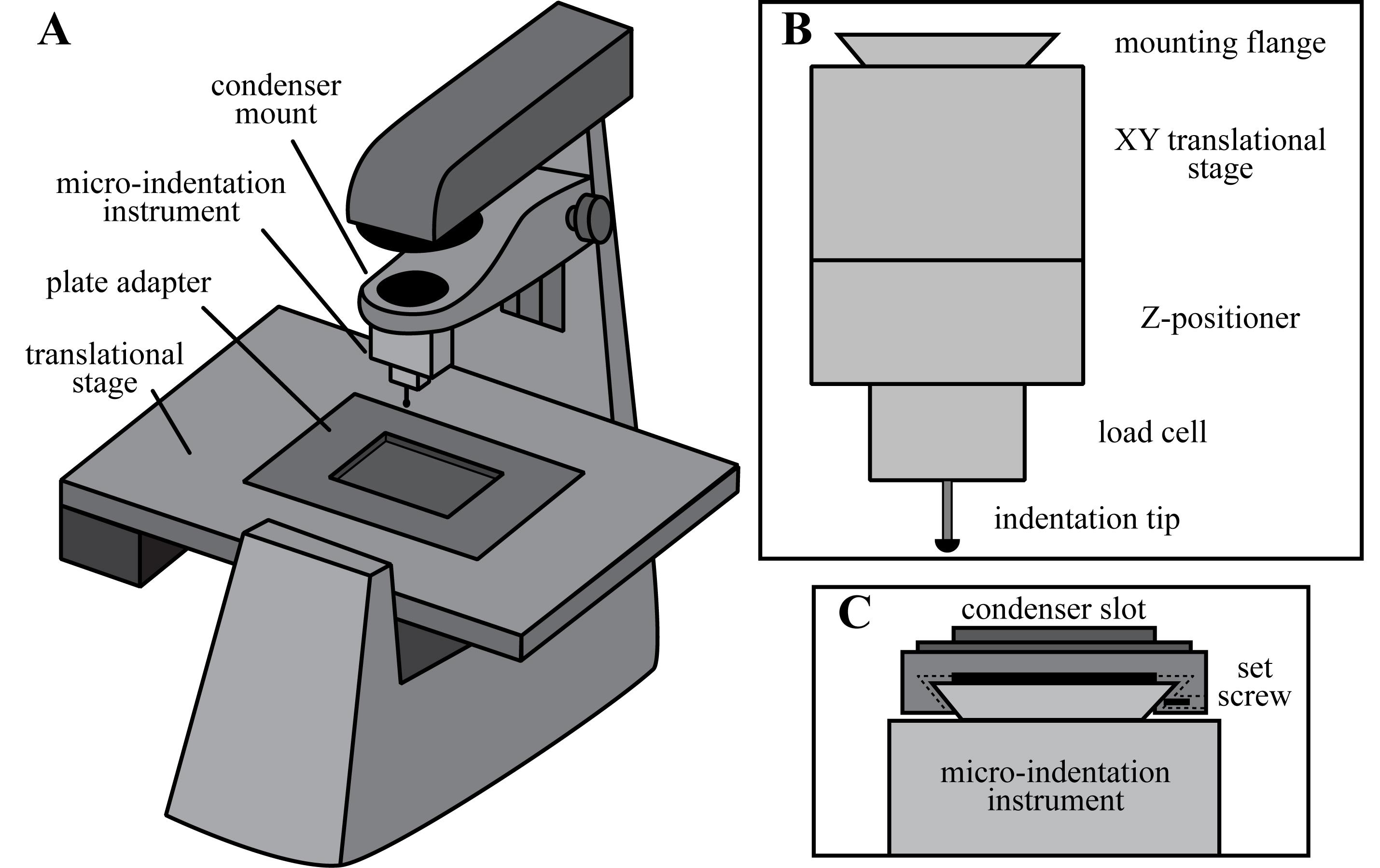
Figure 1. Micro-indentation instrument. A. Bio-indentation measurements are performed using a micro-indentation instrument mounted above an inverted microscope. B. The micro-indentation instrument consists of a hemispherical indentation tip, a load cell to measure the normal force, a vertical Z-positioner with nanometer resolution, a manual XY translational stage, and a dovetail mounting flange. C. The indentation instrument is mounted into the condenser slot of the inverted microscope and secured in place with a hexagonal set screw.
The bio-indentation instrument is mounted on a Nikon Eclipse Ti2-E inverted microscope equipped with a C2+ confocal imaging system and a motorized translational stage. The microscope is configured to capture FITC fluorescence images using the 488 nm excitation laser and a 525/50 dichroic filter cube (Figure 2A). Additionally, confocal reflectance microscopy is used to align the indentation tip directly above the microscope objective prior to the indentation measurement. For reflectance imaging, the 488 nm laser is used as a light source and a reflectance filter cube is installed in the detector unit allowing all light to pass through to the detector channel (Figure 2B).
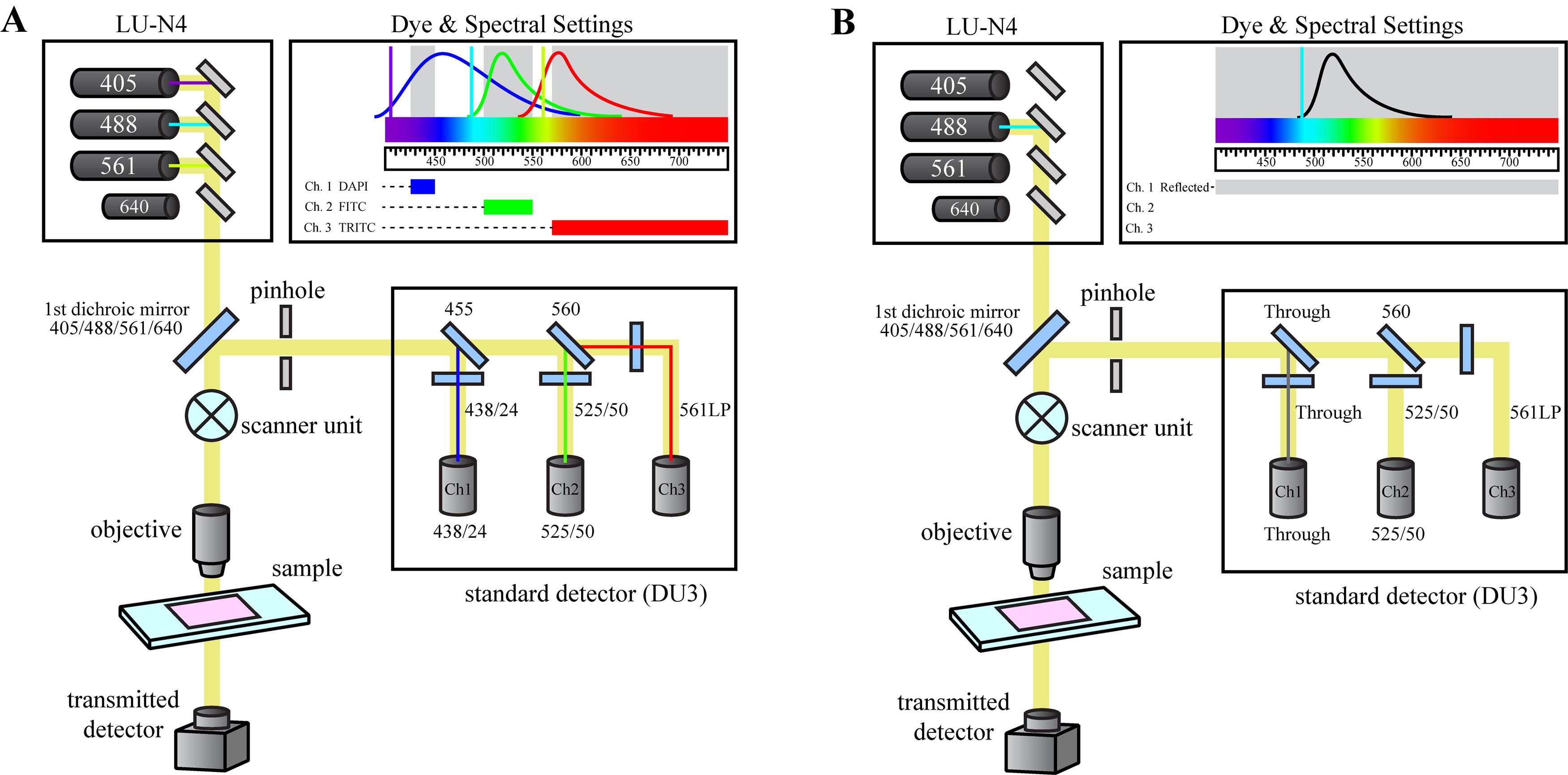
Figure 2. Microscope optical configurations. The Nikon Eclipse Ti2-E Confocal microscope is configured to allow for either (A) fluorescence imaging of the acini structure during the indentation measurement, or (B) reflectance microscopy during the instrumental set-up to determine the center of the indentation tip.
Glass bottom Petri dishes are secured during the indentation measurements using a custom-built Petri dish support plate that fits within the plate adapter of the Nikon Eclipse Ti-2 microscope (Figure 3). The glass bottom Petri dish is positioned over the objective hole in the center of the support plate (1) and is firmly secured using two mounting arms (2). The mounting arms apply pressure to the Petri dish lid to mitigate movement during the indentation measurement. A hole is drilled in the lid of the Petri dish to provide an opening for the bio-indentation instrument. To regulate the temperature during the indentation measurement, the plate is equipped with a thermocouple (3) and nichrome heating wire (4) that are connected to an on-off temperature controller. The power voltage and current settings of the power supply are set to maintain a desired temperature of 37 °C while minimizing the frequency of on-off cycles.
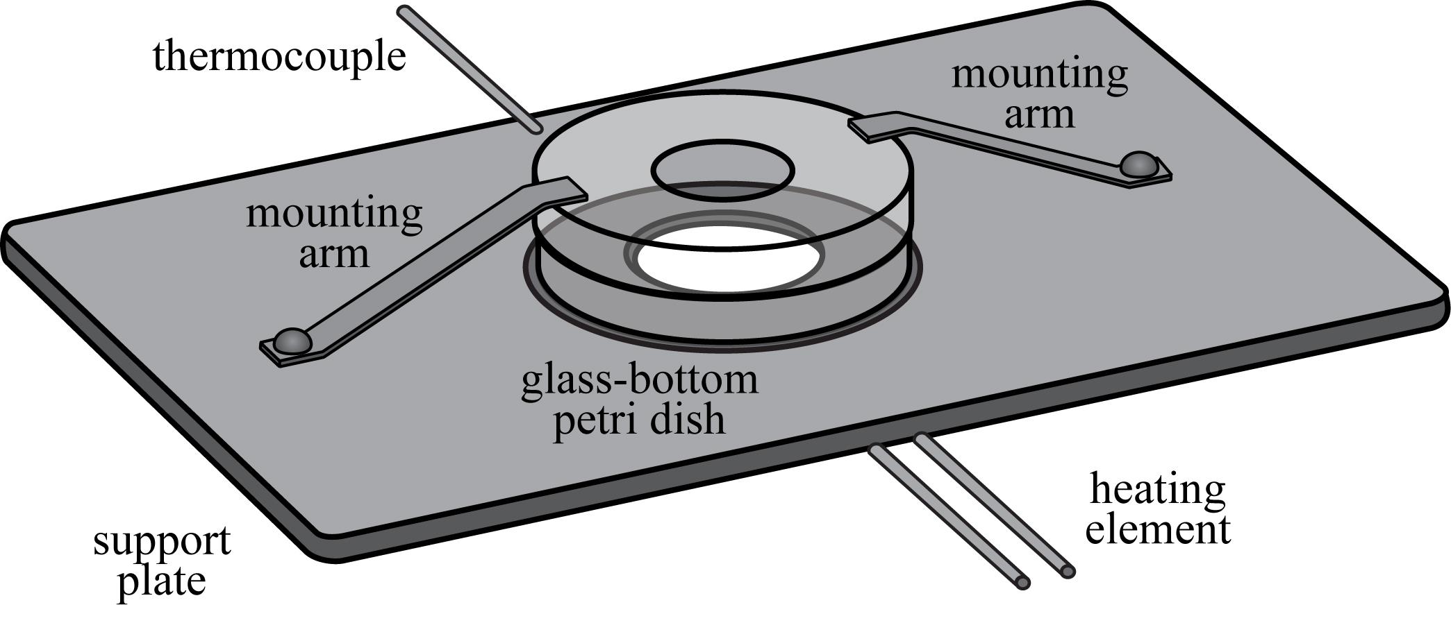
Figure 3. Petri dish support plate. Glass bottom Petri dishes are secured during the indentation measurement using a custom-built support plate that fits into the plate adapter of the microscope’s translational stage. The temperature of the Petri dish is regulated using a temperature controller, a thermocouple, and a nichrome heating element.
Software
The following software is used as part of this bio-indentation protocol and data analysis process:
Nikon NIS-Elements AR imaging software (Version 4.30.02)
National Instruments LabView (Version 2014)
FIJI ImageJ (https://imagej.net/Fiji) (Version 1.52g)
Microsoft Excel (Office 365)
OriginPro graphing software (version 8.5)
Procedure
文章信息
版权信息
© 2020 The Authors; exclusive licensee Bio-protocol LLC.
如何引用
O'Bryan, C. S., Zhang, Q., Lele, T. and Angelini, T. E. (2020). Mechanical Characterization of Glandular Acini Using a Micro-indentation Instrument. Bio-protocol 10(23): e3847. DOI: 10.21769/BioProtoc.3847.
分类
生物物理学 > 生物工程
生物物理学 > 显微技术
您对这篇实验方法有问题吗?
在此处发布您的问题,我们将邀请本文作者来回答。同时,我们会将您的问题发布到Bio-protocol Exchange,以便寻求社区成员的帮助。